Published: January 2001
|
|
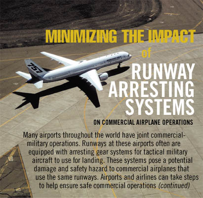
Of the nearly 36,000 airports around the world that are classified as civil, military, or joint-use, approximately 3,800 are used for scheduled commercial service. Worldwide, an estimated 2,000 aircraft arresting systems are installed at facilities in 64 countries. The highest concentration of these systems is on military runways or where the military is a major tenant of a commercial airport. Commercial operators mainly encounter these systems at joint commercial-military airports or when operating charters to military airfields. If the nose-gear spray and gravel deflectors used on some commercial airplanes come in contact with the arresting systems, the deflectors could shatter, creating foreign object debris (FOD). In extreme cases, the FOD could damage a critical airplane system.
To help minimise the impact of runway arresting systems on commercial operations, airlines need to know the following:
- Types of aircraft arresting systems.
- Operational concerns for airlines.
- Measures to help ensure safe commercial operations.
1. TYPES OF AIRCRAFT ARRESTING SYSTEMS
The three basic types of aircraft arresting systems are barriers, cables, and engineered materials arresting systems (EMAS). The first two systems are primarily military systems used for tactical aircraft, such as fighter and attack jets. The third system recently has been developed and is used at commercial airports that do not have sufficient safety areas at the end of the runway. (See "U.S. and International Aircraft Arresting Systems". )
Aircraft arresting barriers. These devices, which do not depend on arresting hooks on aircraft, stop an aircraft by absorbing its forward momentum in a landing or aborted takeoff overrun. These systems are most commonly net devices (fig. 1), but they also include older devices that catch the main gear struts. The barriers typically are located in the overrun of the runway, are unidirectional, and can have collocated or interconnected arresting cables as part of their configuration. They sometimes are used for special purposes, such as stopping the space shuttle.
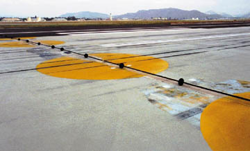
Aircraft arresting cables. Arresting cables span the runway surface and are engaged by the aircraft arresting gear hook (fig. 2). Cables are typically 1 to 1 1/4 in (2.5 to 3.2 cm) in diameter and suspended 1 1/2 to 3 in (3.8 to 7.6 cm) above the pavement surface by rubber donuts 6 in (15.2 cm) in diameter. Used primarily by aircraft built in the United States and Europe, arresting cables have been used by the military since the late 1920s on aircraft carriers and for land-based runways.
Three main factors determine where cables are located on runways: the direction of engagement (unidirectional or bi-directional); the runout of the system, which is the distance from the cable to the point at which the aircraft stops (typically 950 to 1,200 ft, or 290 to 360 m); and whether the system is typically used under visual meteorological conditions or instrument meteorological conditions. Figure 3 shows the typical locations for arresting-cable installations. An aircraft operating on runway 10R would use the cable at the far end for both landing and aborted takeoff unless the aircraft had an emergency, at which point the arresting gear nearest the approach end of the runway would be used.
The installation criteria for cable systems on commercial runways are identified in the U.S. Federal Aviation Administration (FAA) Advisory Circular AC 150/5220-9, Aircraft Arresting Systems for Joint Civil/Military Airports. The location of the cable is marked on the runway by a series of reflective discs 10 ft (3 m) in diameter painted "identification yellow." These discs are laid out with 30 ft (9.1 m) between centres and extend the full width of the runway (fig. 2). (See location identification in "Common Terms")
Engineered materials arresting systems (EMAS). EMAS, which are constructed of high-energy-absorbing materials of selected strength, are located in the safety area, or overrun, of the runway. They are designed to crush under the weight of commercial airplanes as they exert deceleration forces on the landing gear. These systems do not affect the normal landing and takeoff of airplanes. More information concerning EMAS is in FAA Advisory Circular AC 150/5220-22, Engineered Materials Arresting Systems (EMAS) for Aircraft Overruns.
2. OPERATIONAL CONCERNS FOR AIRLINES
Airlines have numerous concerns about operating commercial airplanes on runways with aircraft arresting systems. These include airplane nose-gear interference, trampling of the arresting cable, adjustments to declared distances, dealing with arresting barriers, runway availability, airplane maintenance, and unintentionally engaging arresting systems.
Nosegear interference. Some commercial airplanes have unique nose-gear devices to deflect either spray or foreign objects. A 737-200 that operates on gravel runways has a nose-gear gravel-deflector unit with a ground clearance of 3 1/2 to 6 in (8.9 to 15.2 cm) (fig. 4). The MD-80, MD-90, and 717 airplanes are equipped with a combination nose-gear spray–FOD deflector for normal operations (fig. 5). The ground clearance of this deflector is 3/4 to 1 1/2 in (1.9 to 3.8 cm). A few DC-9-50 airplanes also use the same nose-gear deflector for additional FOD protection. Because most arresting cables are 1 to 1 1/4 in (2.5 to 3.2 cm) in diameter and suspended by rubber donuts 6 in (15.2 cm) in diameter, nose-gear deflectors are at risk of being damaged if a donut is struck.
Normal procedure is for the rubber donuts to be approximately 6 ft (1.8 m) apart, starting 3 ft (0.91 m) from the runway centreline on runways 200 ft (61 m) or less in width. For runways wider than 200 ft (61 m), the donuts are placed 8 ft (2.4 m) apart. To minimise potential damage to the nose-gear deflectors, airplanes with such attachments should slow-taxi over the cable, avoiding the donuts. If the nose-gear spray deflector is damaged and removed, in accordance with the minimum equipment list, the airplane is limited to operating on dry runways until the deflector is replaced.
Trampling of the arresting cable. If an operator considers the trampling, or rolling over, of a cable to be too rough on the airplane, the donuts that elevate the arresting cable above the runway surface can be moved to the sides of the runway during commercial operations. This allows the cable to rest directly on the pavement surface, minimising the bump effect on the airplane.
It is important to note that the cable must be kept under tension, whether lying on the pavement or elevated by the donuts. Otherwise, the cable could be lifted by the airplane landing gear and contact the bottom of the fuselage or antennae located on the lower fuselage. (See rigged and down, rigged and up, and out of battery in "Common Terms")
Adjustments to declared distances. Some airlines that operate on runways with arresting cables have reduced the available runway length by the distance from the operational end of the runway, or threshold, to the cable. For example, an 8,000-ft (2,438-m) runway could be reduced to 5,000 ft (1,524 m) of usable runway length for each of the following declared distances: takeoff distance available, takeoff runway available (TORA), accelerate stop distance available, and landing distance available (fig. 6).
If the distance between the threshold and the cable is not used, however, the remaining runway substantially reduces the available payload on a 737-800 and MD-83 operation, based on the conditions of a standard day, optimal flap setting, zero wind, no obstacles, and zero slope (table 1). This method may be usable for a short-haul flight, but it is not a preferred long-term solution.
Dealing with arresting barriers. Nets are typically located in the overrun area near the runway threshold. If the net is in the raised position at the departure end, it should be treated as an obstruction that has to be cleared by 35 ft in accordance with the FAA federal aviation regulations and an adjustment made to the TORA. There are rare situations in which a net has been located in the actual runway. In these cases, provided the net lies flat on the runway and is under tension, it can be rolled over. If the net is bunched and lying on top of the runway, the airplane should not cross it.
Runway availability. A commercial airplane following a military aircraft could experience a delay landing if the military aircraft engages the arresting gear. The flight crew of the commercial airplane should expect to execute a missed approach while the military aircraft is removed and the arresting gear reset. Typical cycle times for arresting gear can vary from 3 to 10 minutes depending on the type of system. (See cycle time and reset time in "Common Terms".)
Airplane maintenance. If the flight crew believes the airplane nose-gear has contacted one of the hard rubber donuts supporting an arresting-gear cable, a visual inspection of the nose-gear spray deflector should be conducted to verify whether it has been damaged. A similar visual inspection would apply if the flight crew thought that the cable had made contact with the belly of the airplane. For airlines that routinely operate on runways with arresting-gear cables, additional visual inspections may be conducted depending on the type of arresting systems installed and to what extent the airplane interacts with the system.
Unintentionally engaging arresting systems. Occurrences of commercial airplanes being engaged or tangled in arresting cables are rare. In the 1970s, a DC-10 had a rejected takeoff during a flight test. In this case, the fuse plugs on the leading tires on one main landing gear had deflated, and during the takeoff roll the arresting cable was snagged, causing the airplane to stop.
In 1995, an MD-88 was starting its takeoff roll when the nose landing gear snagged the arresting gear, bringing the airplane to a halt. It was inspected with no damage found and dispatched shortly thereafter.
3. MEASURES TO HELP ENSURE SAFE COMMERCIAL OPERATIONS
The key to dealing with the presence of arresting cables on runways is coordination among the airline operator, the airport operator, and the agency having control of the arresting system. Educating the various parties on the operational needs of commercial airplanes can alleviate many limitations. Six ways to minimise the impact of arresting systems located on runways used by commercial airplanes are shown in the following list.
- If the airport has parallel runways, normally only one of the two runways has the arresting systems installed. Consider limiting commercial operations to the runway without the arresting systems.
- Coordinate the permanent removal of the arresting systems. The military aircraft using the runways may no longer need the arresting gear; the gear, or at least the cable, could be removed. (See derigged in "Common Terms".)
- Install a system to raise and lower the arresting cable flush into a track on the runway (fig. 7). This modification, referred to as BAK-14, takes an existing arresting cable and allows the air traffic control tower to remotely raise the arresting cable for military operations and lower it into a track flush-mounted on the runway for commercial operations. At the majority of joint-use airports in the United States, this modification has been made to the standard BAK-9/12/13 systems that previously were supported by the rubber donuts. (See BAK in "Common Terms".)
- Disconnect the cable and lay it on the side of the runway during periods of commercial operations (fig. 8). This is a workable solution provided the scheduled commercial operations do not interfere with the flight schedule of the military aircraft. Or slide the rubber donuts to the edge of the runway so that the cable lies flat on the pavement but is still under tension. The airplane then can roll over the top of the cable.
- Although not considered an optimal solution, the runway length can be reduced. This is feasible if the runway is of sufficient length that the mission of the airplane can be achieved on the usable runway distance between arresting gears installed at each end of the runway. At a minimum, operators may consider reducing only the distance from the approach end of the runway to the gear.
- Operators may wish to increase the frequency of maintenance inspection of the nose-gear and lower fuselage areas for airplanes that routinely operate over arresting-gear cables.
SummaryCommercial airplanes can safely use runways with aircraft arresting systems. Safe operation requires planning by, and coordination among, commercial airplane operators, airport authorities, and the agencies that control the arresting systems. |
BRAD BACHTEL
LEAD, AIRPORT OPERATIONS
AIRPORT TECHNOLOGY
BOEING COMMERCIAL AIRPLANES GROUP
| Top of page | Boeing Home | Boeing Commercial | Contact Aero |
Aero Copyright © The Boeing Company. All rights reserved.