Published: October 2001
|
|

Boeing has developed flight deck displays that enhance the ability of the flight crew to monitor the navigational state of the airplane. These lateral navigation (LNAV) and vertical navigation (VNAV) deviation scales provide the flight crew with an improved indication of current position relative to the desired track and the available deviation allowance. Understanding how the new 737-600/-700/-800/-900 flight deck displays take full advantage of airplane system capabilities requires a discussion of the following:
- Required and actual navigation performance.
- Budget for technical error.
- LNAV and VNAV deviation scales.
1. REQUIRED AND ACTUAL NAVIGATION PERFORMANCE
Three concepts need to be understood when discussing required navigation performance (RNP) operations: the RNP required by a regulatory agency for a defined flight path, the RNP rating of a given airplane model, and the actual navigation performance (ANP) of an airplane during flight. The first two concepts often are referred to as RNP.
RNP extends the capabilities of modern airplane navigation systems by providing a precise characterisation of airplane navigation performance. The navigation accuracy of an airplane is based on its system capabilities rather than specific ground-based navigation aids. RNP defines the navigation accuracy that an airplane must have to operate on a specific route segment. (See "Required Navigation Performance for Improved Flight Operations and Efficient Use of Airspace," in Aero no. 12, October 2000.)
The navigation accuracy required for a particular flight phase varies. For example, the accuracy can be 4.0 nm for oceanic airspace or 0.1 nm for near category I approaches. The specific RNP for a particular flight path ensures that airplanes with adequate navigation accuracy remain within a defined pathway or containment boundary. This boundary provides safe separation from terrain, other airplanes, and adjacent airspace. The RNP values for flight phases are stored in the airplane's flight management computer (FMC) database and are available to the flight crew as a digital readout on the control display unit (CDU).
The flight crew can override the RNP values, both lateral and vertical, for specific situations in which the database RNP value is not applicable. (Page 4 of the RNP PROGRESS pages, displayed on the CDU, reviews all relevant components of total system error and flight crew override of RNP for lateral and vertical navigation. It also gives a preview of the lateral and vertical RNP values for the approach in the FMC flight plan.)
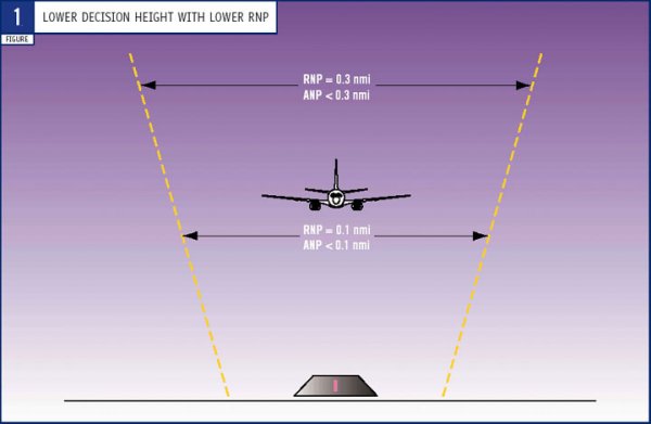
To determine whether an airplane is eligible to fly in a given RNP-defined airspace, the flight crew must know the RNP rating of the airplane. RNP ratings vary by model and operational mode. The 737 has the lowest RNP rating of all Boeing models for each of the three defined operational modes: autopilot, flight director (FD), and hand flown. Lower RNP ratings for an airplane, when overlaid onto RNP-defined airspace, result in lower decision heights (figure 1).
If RNP is a measure of how good the airplane's navigation system must be, then ANP is the estimated real-time measure of how good the airplane's navigation system actually is. Whereas RNP defines the allowable airplane error in terms of distance and probability relative to the procedurally defined path, ANP is based on probable airplane position determination and on guidance errors.
On Boeing airplanes, multiple sources of navigation data are integrated to determine the system navigation solution. Inertial systems initially are very accurate but may tend to drift if not updated accurately throughout the flight. Global positioning system (GPS) units generally provide exceptionally accurate data but must be monitored for undetected failures and lack of satellite coverage. Ground-based radio navigation aids vary in accuracy and availability.
These sources of data are analysed continuously by the FMC to calculate the best estimate of current airplane position and estimated airplane position uncertainty. If any one source is deleted, the confidence in the navigation position will decrease. Thus, the ANP value will increase. Displaying ANP can be a great help to the flight crew when trying to verify airplane position because the crew no longer must tune, identify, and cross-plot navigation aids. The FMC logic uses the best sources of data available to provide the flight crew with a real-time navigation solution. (See "ANP Algorithms" and "Navigation and Time".)
Neither RNP nor ANP contains any data that indicate how close the airplane is flying to the desired track. RNP tells the flight crew how accurate the navigation system needs to be, and ANP tells the flight crew how accurate the system currently is. RNP and ANP do not indicate to the crew where the airplane is relative to the centre of the desired flight path. To explain how ANP and RNP relate to the relative position of the airplane requires a discussion of the concept of error budget.
2. BUDGET FOR TECHNICAL ERROR
To fly safely on the designated flight path, the airplane navigation system must ensure that the airplane remains within the RNP-specified airspace. Three potentially significant sources of error are considered in the analysis of the airplane navigation system: path computation error, navigation system error, and flight technical error.
Path computation error.
Path computation error is a measure of how closely the airspace definition of the flight path matches that used by the FMC. This error is not significant when both the FMC and the route designers use the same coordinate reference to define the path end points. When the route designers and the FMC use the same geodetic survey reference, the contribution of path computation error to total system error is small enough that it need not be included in the navigation system error.
Navigation system error.
Navigation system error indicates how well the airplane position, as determined by navigation sources, matches the true airplane position. The statistical navigation system error is characterised by ANP. Because the airplane's navigation sources and sensors are not perfect, a difference, or error, may exist between the estimated, or calculated, airplane position and the actual airplane position. If system failures or flight crew selections reduce the number or degrade the quality of the navigation sources, ANP will increase. For example, an ANP value of 0.06 nm means that the airplane very probably is within a 720-ft-diameter circle of its estimated position. If this is the only error in the total navigation system, the runway probably will be at most 360 ft to the left or right when the airplane breaks out of the clouds at the minimum descent altitude.
Flight technical error.
Flight technical error (FTE) is a measure of how well the airplane is tracking the lateral and vertical paths estimated by the navigation system. The flight crew observes FTE with deviation scales by using digital CDU readouts or by noting how far the airplane symbol on the navigation display is off the route. FTE is the one component of the error budget that can be controlled by the flight crew. (See "Flight Technical Error" box.)
To ensure that the airplane remains on the desired path, the flight crew limits the errors in total navigation performance over which it has control and monitors the errors that it cannot control. FTE can be controlled by the flight crew and should be minimised. Navigation system error cannot be controlled by the flight crew but should be monitored to ensure that it remains within acceptable limits. Path computation error cannot be monitored or controlled but generally is sufficiently small that it can be ignored.
3. LNAV AND VNAV DEVIATION SCALES
Boeing has developed flight deck displays that enhance the ability of the flight crew to monitor the dynamic relationship among ANP, RNP, and current flight path deviations. The LNAV and VNAV deviation scales — which are based on the familiar concepts of a centreline indication, scale limits, and a deviation pointer — incorporate additional symbols to provide the flight crew with a clear indication of current position in relation to desired position and the total allowable error budget (figure 2).

The LNAV deviation scale is active anytime LNAV is in the engaged FD or autopilot mode. If ANP is a relatively small portion of the total allowable error for a given flight path, then room exists in the error budget for the flight crew to purposely increase FTE. For example, if RNP is 4.0 nm and ANP is 0.05 nm, then the flight crew could deviate from track by 3.94 nm (to miss a thunderstorm, for example) without requesting a deviation. The allowable deviation from centreline and the limit are clearly indicated on the LNAV deviation scale (figure 3).

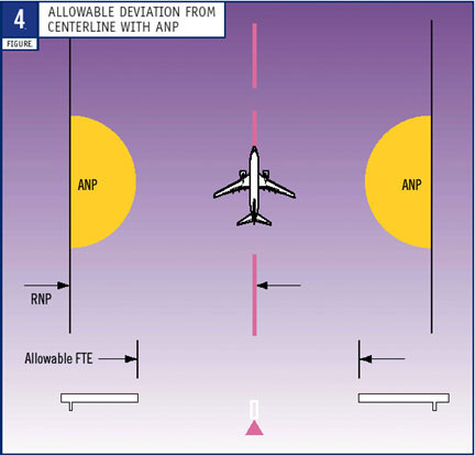
On the other hand, when the ANP value is relatively large and begins to approach RNP, the flight crew does not have room to deviate from the desired track and still remain within the desired route constraints. This is best illustrated in the final approach environment, where RNP may be 0.1 nm and ANP may be 0.08 nm. In this case, the allowable flight crew error from centreline would be only 0.02 nm, or 120 ft. The deviation scale would clearly show that ANP is a large percentage of RNP and that the flight crew has a very small margin for technical error (figure 4).
When ANP equals RNP, it is not possible to ensure that the airplane is within the desired navigational limits, and an alternate plan must be executed. This case will result in an appropriate indication on the scale and a concurrent UNABLE REQD NAV PERF-RNP message (figure 5).

The same scale also is presented for the vertical path. A maximum deviation indication is presented by flight leg. When RNP or ANP is defined for the vertical path in the technical standards, the vertical scale uses the same philosophy as the LNAV deviation. Because the LNAV and VNAV deviation scales provide enhanced awareness and alert the flight crew to the position of the airplane, the RNP rating of the airplane can be reduced. Current estimates indicate that the RNP rating of 737-600/-700/-800/-900 airplanes can be reduced to approximately 0.10 nm for autopilot command and FD LNAV.
Transition to traditional runway approach.
The best method for providing precision guidance to the end of the runway is to move to a precision-approach mode, perhaps as close as 3 nm before the runway threshold. The integrated display enables the airplane to be stabilised on all parameters at 500 ft above ground level, a tried and true value for safe landings. The best FD and autopilot mode for the final 500 ft of the approach is the approach mode. The LNAV and VNAV deviation scales provide for a smooth transition to an instrument landing system (ILS) final approach by displaying final approach anticipation cues.
For example, using LNAV and VNAV, the flight crew can fly a precise path over the ground toward the final approach leg. When the flight crew tunes an ILS, ghost pointers (which resemble raw data ILS deviation pointers) appear where the ILS deviation pointers typically would be observed. The LNAV and VNAV scales continue to be active as long as LNAV and VNAV are in the active mode. As the current path converges to the final path, the ghost pointers move toward their respective scale centres. If the approach mode is armed, the flight mode annunciations will change to the appropriate ILS modes for the final approach guidance as the ILS localiser and glide slope are captured. The traditional ILS deviation scales then replace the LNAV and VNAV scales.
SummaryOperators of 737-600/-700/-800/-900 airplanes can now implement a new navigation feature that provides flight crews with increased operational capability and enhanced situation awareness. The new LNAV and VNAV deviation scale displays are available on 737-600/-700/-800/-900 airplanes in production and by retrofit. Application of the system on other Boeing models currently is under consideration. |
MICHAEL CARRIKER
CHIEF PROJECT PILOT
FLIGHT OPERATIONS
BOEING COMMERCIAL AIRPLANES
DARCY HILBY
PRINCIPAL ENGINEER
FLIGHT CREW OPERATIONS INTEGRATION
BOEING COMMERCIAL AIRPLANES
DREW HOUCK
ASSOCIATE TECHNICAL FELLOW
FLIGHT DECK DISPLAYS
BOEING COMMERCIAL AIRPLANES
H. ROLAN SHOMBER
ASSOCIATE TECHNICAL FELLOW
FLIGHT MANAGEMENT COMPUTERS
BOEING COMMERCIAL AIRPLANES
| Top of page | Boeing Home | Boeing Commercial | Contact Aero |
Aero Copyright © 2003 The Boeing Company. All rights reserved.