Published: October 2002
|
|
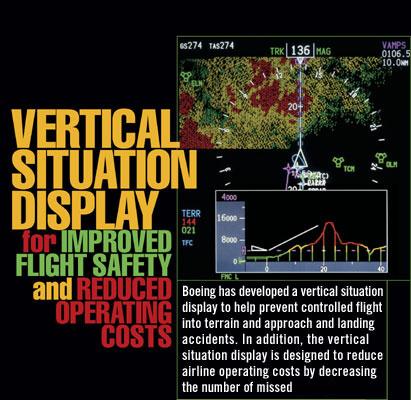 ...approaches, tail strikes, and hard landings and by reducing vertical navigation training time.
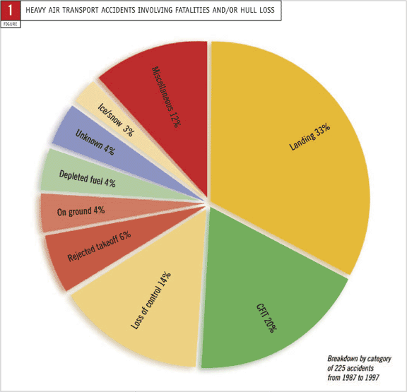
Of the more than 200 heavy air transport accidents involving hull loss or fatalities in the past 10 years, more than 50 percent were associated with either controlled flight into terrain (CFIT) or the approach and landing phases of flight (fig. 1). Many of these accidents involved inadequate or loss of vertical situation awareness by flight crews.
To help prevent CFIT and approach and landing accidents, Boeing has created a clear graphical picture of the airplane vertical flight path that enhances the flight crews' overall situation awareness. This vertical situation display (VSD) works in conjunction with the terrain-mapping feature of the terrain awareness and warning system (TAWS) (e.g., the Honeywell enhanced ground proximity warning system) to provide flight crews with an intuitive presentation of the vertical situation relative to the surrounding terrain and the final approach descent path. In addition to terrain alerting, the TAWS provides a lateral, or top-down, view of terrain. The VSD depicts a profile, or side view, of terrain and flight path data.
The VSD is designed to maximise safety while minimising required changes to airplane hardware and airline flight operations and training. It also capitalises on airplane design elements common across all Boeing models and can be implemented within the constraints of available space on existing airplane displays.
The VSD will be offered by early 2003 as a customer option on in-production 737s and by retrofit on 737-600/-700/-800/-900 airplanes already in service. Implementation of the system on other Boeing models is under consideration.
The value of the VSD can best be understood through a discussion of the following:
- Current method for assessing vertical situation.
- Development of the VSD.
- Display features.
- Benefits of the VSD.
- Implementation on Boeing airplanes.
1. CURRENT METHOD FOR ASSESSING VERTICAL SITUATION
Currently, flight crews must assimilate vertical situation information from various sources to create a mental picture of the vertical profile. These sources include barometric and radio altitude readouts, the vertical speed indicator, ground proximity warning systems, terrain depiction systems, and navigation information from the flight management computer (FMC) and navigation charts. Flight crews usually are very effective at integrating this information. However, they can be hard-pressed to formulate and maintain a completely accurate mental model of the vertical profile, especially during time-critical or high-workload situations or during initial training using vertical navigation (VNAV) systems. This makes misinterpretation of the vertical situation more likely.
During the past several years, various options have been investigated to provide vertical situation information on the flight deck. Although many new technologies promise to deliver improved overall situation awareness, significantly enhancing the safety of the worldwide commercial airplane fleet will require cost-effective solutions that are relatively easy to retrofit. Presenting flight crews with a side view of the vertical dimension is one such solution—it targets a significant part of the problem yet involves only minor changes to the airplane and airline infrastructure.
2. DEVELOPMENT OF THE VSD
Boeing evaluated various methods of improving vertical situation awareness with the goal of reducing the overall accident rate of the commercial air transport industry. Because the measurement of vertical awareness is subjective and there is no one-to-one correlation between vertical awareness and accident prevention, Boeing decided that measurements of vertical situation awareness alone are insufficient for evaluating the safety of various technologies. Instead, databases—such as those of airline incident reports and accident reports for the past 10 years—were used as one source of evaluation criteria. The incident reports were used to guide the direction of concept development, whereas the accident reports were used to determine the expected effect of specific concepts on the accident rate.
In addition, flight crews flew three types of scenarios in an engineering flight deck simulator that reflected the target accident types (i.e., CFIT and approach and landing). The scenarios involved an approach during which the airplane must descend later than normal to intercept the glideslope, an approach with a steep glideslope, and level flight toward mountainous terrain. Flight crew performance, subjective ratings, and observations were gathered.
Results showed that the VSD was the most effective display format in all three scenarios. The least effective display was a simple three-dimensional (3D) perspective display. The VSD scored high in the areas of early threat recognition, effectiveness when flying steep approaches, and maintenance of a stabilised path.
Based on these results, Boeing chose to pursue further development of the VSD as the most effective and practical option that could be implemented in the near term. This decision was not meant to preclude further developments in 3D perspective displays.
Developing a side-view vertical profile display necessitated refinement of the human interface requirements. Boeing worked with airlines, suppliers, and regulators to ensure efficient development and implementation as well as the establishment and support of an industry standards team. Human interface requirements were refined in the 737 engineering flight deck simulator because the 737 uses various display types and sizes. Boeing wanted to ensure that any VSD design could be implemented on the many sizes of electronic displays used today, including the larger ARINC D-size (8- by 8-in) and the smaller ARINC B-size (6- by 7-in) displays.
3. DISPLAY FEATURES
A VSD graphically represents a view of the vertical profile of the airplane. The Boeing VSD depicts a swath that follows the current track of the airplane and therefore is referred to as a tracktype VSD. When selected by the flight crew, it appears at the bottom of the navigation display (fig. 2).
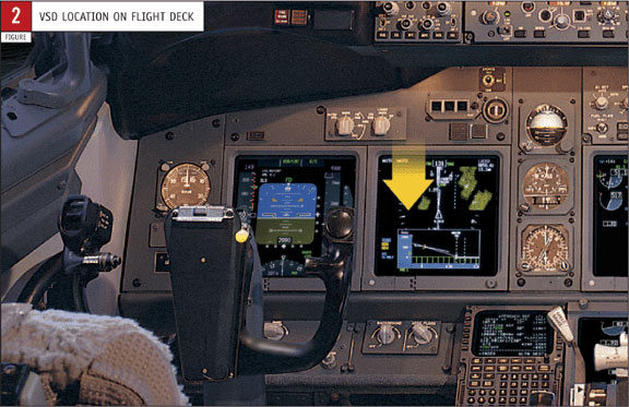
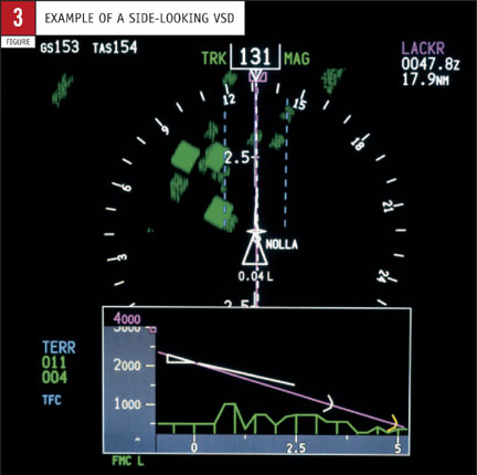 Figure 3 shows an example of the Boeing side-looking VSD. The basic features of this VSD include altitude reference and horizontal distance scales, an airplane symbol, a vertical flight path vector, terrain depiction, navigation aids, glideslope depiction, and various information selected by the flight crews and FMC such as the mode control panel (MCP)–selected altitude, minimum decision altitude, and selected vertical speed predictor.
The development of the VSD format involved a thorough human-centred design approach. All the features had to meet basic flight deck philosophies and design guidelines. In addition, because clutter always is a concern, each feature was added only after it was shown to provide a significant benefit in terms of enhancing flight crew awareness. Some of these human-centred design requirements included the following:
- Information had to be consistent with that which already appears on other flight displays.
- Information had to be intuitive and follow standard flight information system and navigation display conventions.
- The display had to use existing symbols to as great a degree as practical.
One issue identified with the track-type VSD was that flight crews wanted additional terrain look-ahead in the direction of a turn. An algorithm was invented that expands the swath in the direction of the turn to give flight crews the desired result.
Wherever appropriate, symbols from other displays were incorporated into the VSD. For example, the symbol for MCP-selected altitude is the same shape as the corresponding symbol on the primary flight display altimeter tape.
Although the VSD can be used to assess path stability, path stability is only part of the equation for a stable approach. The other factor is speed stability. To facilitate speed stability, a new symbol was introduced on the VSD. The range-to-target speed symbol is a green dot that shows where excess speed will be dissipated along the vertical flight path vector. If excess speed is not an issue, then the symbol will not appear on the display.
The display remains stable during dynamic conditions. Flight crews should keep in mind that the VSD is a supplementary display and as such is not intended for use as the primary reference during dynamic manoeuvres and procedures.
Incorporating the VSD does not require any changes to flight operations procedures, except for the addition of procedures that apply to the VSD in non-normal conditions. Additions to the airplane flight manual describe the features of the VSD. Flight crew training regarding the VSD only involves written materials.
4. BENEFITS OF THE VSD
The main benefit of the VSD is improved safety. The VSD will give flight crews an intuitive view of the vertical situation just as the current map display provides an intuitive depiction of the lateral situation. In conjunction with the other safety features of the flight deck, this increased vertical situation awareness helps prevent CFIT and approach and landing accidents and incidents, thereby further decreasing the already low accident rate of the worldwide commercial airplane fleet.
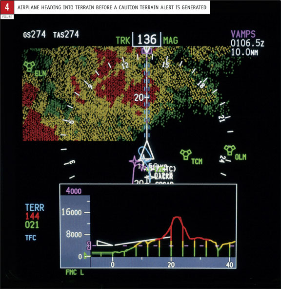
The VSD depicts terrain information from the TAWS or other onboard sources from another perspective. The TAWS generates a lateral view of the surrounding terrain and provides terrain proximity alerting. The VSD depicts the vertical dimension of the terrain (fig. 4), which will allow crews to recognise possible terrain conflicts more readily, before a TAWS alert is generated.
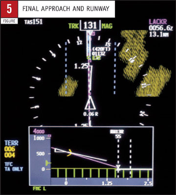 The VSD also depicts the final approach segment of the intended path of the airplane to the runway (fig. 5), thereby assisting flight crews as they establish the glide path. Terrain alerting from the TAWS is disabled gradually during this phase of flight to eliminate nuisance alerts, but the VSD is available full time.
The VSD also complements the increased use of constant-angle, area navigation, and required navigation performance (RNP) approaches by providing immediate validation of the selected approach path and allowing full-time monitoring of the airplane position relative to the selected glide path. As low-altitude, in-cloud manoeuvring becomes commonplace and RNP criteria allow better utilisation of restricted airspace, the VSD will serve as an invaluable confirmation of airplane performance.
The VSD will provide additional operational benefits. Earlier recognition of terrain clearance problems facilitates more timely go-arounds and earlier CFIT avoidance. In addition, with improvements in vertical awareness, flight crews have an improved ability to monitor the vertical path. Earlier recognition of unstabilised approaches helps reduce the number of go-arounds and missed approaches. Because many unstabilised approach problems are manifested during the landing phase of flight, earlier recognition also should reduce the number of hard landings, runway overruns, brake fires, and tire failures. This will help reduce airline operating costs by extending the life of the airframe structure, landing gear system, tires, and brakes and by reducing the airplane maintenance downtime associated with landing problems.
Finally, the intuitive nature of the VSD will allow flight crews to assess the vertical situation quickly, thus reducing overall workload. Crews will have more time during the most critical phases of flight—climb, descent, and final approach—to focus on other routine tasks and handle any unusual circumstances they may encounter.
5. IMPLEMENTATION ON BOEING AIRPLANES
The VSD has only recently become a viable option for increasing vertical situation awareness. Three factors precluded an earlier introduction of the technology. The information presented on the VSD must be accurate. Accuracy requires a good terrain database, and that technology has become available only recently for commercial applications.
Second, flight crews must have confidence in the accuracy of the position of the airplane relative to physical features. Although most navigation systems are very reliable and robust, the advent of the global positioning system has improved lateral and vertical accuracy of the airplane position.
Finally, as a result of improvements in display technology and computational throughput, the quantity of display symbols is not as limited as it once was.
The VSD was designed for incorporation within the constraints of current production models. Implementation on in-production airplanes requires system changes to the avionics displays, FMC, and TAWS. For the avionics displays, the display system software must be updated. The FMC requires a software upgrade, and new hardware and software are required for the TAWS. In-service airplanes may require additional hardware upgrades to allow full implementation.
The introduction of new, large liquid crystal display screens on Boeing airplanes facilitates implementation of the VSD. The VSD also was designed to be compatible with cathode ray tube–based flight decks. Although Boeing has focused on integrating the VSD into the flight deck, a large portion of the worldwide fleet in the next 5 to 10 years still will use electromechanical instrument flight decks. The VSD can be implemented on these flight decks as a stand-alone display system. These retrofit solutions are in development.
Boeing has developed the VSD so that additional features can be added. One example is the depiction of the vertical profile along the entire planned flight path. Showing the vertical swath along the planned flight path of the airplane, instead of just along the current track, provides several benefits. Not only may this enhance awareness of the vertical mode, but VNAV and lateral navigation concepts also may be simplified for training. Other envisioned enhancements include providing weather and traffic information.
SummaryThe VSD is another step on the evolutionary path of flight deck displays. The display is a natural complement to and outgrowth of the lateral moving map introduced into commercial fleets in the 1970s and 1980s. The VSD can have a significant and beneficial effect on commercial air transport safety. By presenting the flight crew with a simple graphical picture of the vertical dimension, vertical situation awareness is enhanced, which potentially can significantly reduce the number of air transport accidents in the worldwide fleet in a realistic time frame. The VSD can be implemented without major airplane hardware changes. The system will be offered by early 2003 as a customer option on in-production 737s and by retrofit on 737-600/-700/-800/-900 airplanes already in service. Implementation of the system on other Boeing models is under consideration. |
DAVID CARBAUGH
CHIEF PILOT
FLIGHT OPERATIONS SAFETY
BOEING COMMERCIAL AIRPLANES
SHERWIN CHEN
ENGINEER
FLIGHT DECK ENGINEERING
BOEING COMMERCIAL AIRPLANES
ALAN JACOBSEN
TECHNICAL FELLOW
FLIGHT DECK ENGINEERING
BOEING COMMERCIAL AIRPLANES
ROBERT MYERS
MANAGER
FLIGHT DECK ENGINEERING
BOEING COMMERCIAL AIRPLANES
JOHN WIEDEMANN
ASSOCIATE TECHNICAL FELLOW
FLIGHT DECK ENGINEERING
BOEING COMMERCIAL AIRPLANES
| Top of page | Boeing Home | Boeing Commercial | Contact Aero |
Aero Copyright © The Boeing Company. All rights reserved.