Electrics - Right Engine & APU Show Schematic only

DC Electrical System Airplanes with 90-minute standby power - The main and APU batteries are paralleled if power is lost at the left 28 volt DC bus. APU Battery main Battery Battery Switch Battery Discharge Lights Static Inverter Standby Power Selector Switch Standby Power OFF Light Hot Battery Buss Battery Bus Standby DC Bus Standby AC Bus Left Main DC Bus Right Main DC Bus Centre Buses As Installed Power will transfer providing at least 2 generators are operating and 3 autopilots armed for approach If there is a loss of power on one of the two DC buses, the DC BTB will close automatically. AC Electrical System Stop APU Connect External Power Start Left Engine Stop Right Engine AC Buses and Load Shed System Generator Drive Disconnect Generator Drive Disconnect AC Bus Tie System AC Bus Tie System Generator Control Switch Generator Control Switch Ground Service Switch Ground Service Bus Ground Handling Bus - The Ground Handling Bus can only be powered on the ground by the APU or External Power. It cannot be powered from the engine-driven generators Left AC Bus OFF Light Right AC Bus OFF Light Left Flight Instrument Transfer Relay Right Flight Instrument Transfer Relay Left AC Bus Right AC Bus Captain's Flight Instruments Transfer Bus First Officer's Flight Instruments Transfer Bus

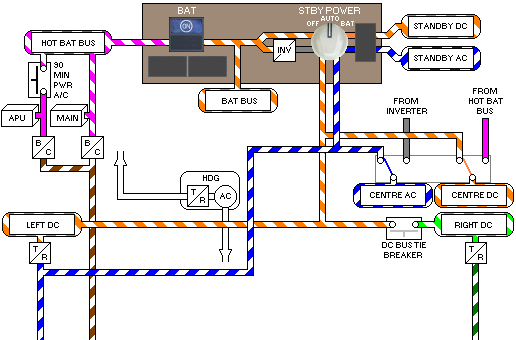
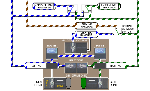
The Generator Control Switches are normally left ON. Therefore if the right engine is started first, the generator breaker closes automatically after the right Bus Tie Breaker opens. The engine then powers the right buses and the APU Generator or External Power supplies the left buses.