Electrics - Main AC & DC Power 
The electrical system generates and distributes AC and DC power to other airplane systems, and is comprised of:
- Main AC and DC system.
- Battery/Standby Power System
- ETOPs fitted - Hydraulic Driven Generator.
System operation is automatic. Electrical faults are automatically detected and isolated.
Main AC Electrical System
The AC electrical system is the main source for airplane electrical power.
AC Electrical System Power Sources
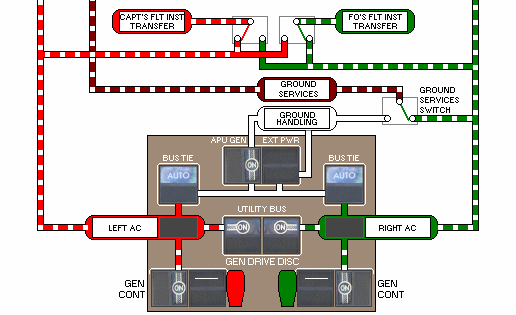
The entire airplane AC electrical load can be supplied by any two main airplane AC power sources. The main airplane AC electrical power sources are:
- Left and right engine Integrated Drive Generators (IDGs).
- APU generator.
The entire airplane AC electrical load also can be supplied by External Power.
The power sources operate isolated from one another and cannot be paralleled. For most normal operations, both engine driven generators are available. To use both at the same time, the electrical system is divided into two sections, left and right. As a result, each engine driven generator powers an essentially independent electrical system.
Integrated Drive Generators
Each engine has an IDG which combines a generator driven by a Constant Speed Drive Unit (CSDU). Each IDG has automatic control and system protection functions.
Power from the generator is routed to the main AC bus through the Generator Control Breaker. When an engine starts, with the GEN CTRL switch selected ON, the Generator Control Breaker closes and the IDG automatically powers the respective Main AC Bus. The previous power source is disconnected from that bus.
 The IDG can be electrically disconnected from the buses by pushing the respective GEN CTRL Switch to OFF. Selecting OFF opens the generator control breaker and resets fault trip circuitry. The IDG can also be electrically disconnected from its respective bus by selecting External Power prior to engine shutdown.
 The OFF Light in the GEN CTRL switch illuminates, and the EICAS Caution message L or R GEN OFF displays whenever the generator control breaker is open.
 The DRIVE light illuminates and the EICAS Advisory message L or R GEN DRIVE displays when:
- low oil pressure is detected or
- high oil temperature is detected in an IDG.
The IDG drive can be disconnected from the engine by pushing the respective DRIVE DISC switch. The IDG cannot be reconnected by the flight crew.
APU Generator
The APU generator is electrically identical to the IDG generators. The APU generator can power either or both main buses, and may be used in flight as a replacement to an IDG source SCHEMATIC.
Electrical power from the APU generator is routed through the APU generator breaker. When the APU Generator Control Switch is ON, the APU generator breaker operates automatically.
If no other power source is available when the APU generator becomes available, the APU generator automatically connects to both main AC buses through the Bus Tie Breakers. If the External source is powering both main buses, the external source continues to power both main buses.
If only one engine-driven generator is powering both the left and right systems when the APU generator becomes available, it causes the operating generators' BTB to open. This isolates the generator, but does not trip it off. The APU the powers one side of the system while the operating generator powers the other SCHEMATIC.
Selecting OFF:
- Opens the APU Generator control breaker
- Resets fault trip circuitry
The APU Generator OFF light illuminates, and the EICAS advisory message APU GEN OFF displays when:
- the APU is operating and the APU Generator Control Breaker is open because of a fault or
- the APU GEN switch is selected OFF.
When the APU Generator switch is ON and a fault is detected, the APU Generator cannot connect to the buses.
External Power
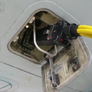 A receptacle aft of the nose wheel well is used to connect external ground power to the airplane. External power can power the left and right main buses, and can be used instead of APU power. Both cannot be used simultaneously SCHEMATIC. External power must be manually selected.
 When the external power source voltage and frequency are within limits, the external power AVAIL light illuminates. When the AVAIL light is illuminated, the EXT PWR switch controls the External Power Contactor (EPC).
Pushing the EXT PWR switch ON connects external power to both main buses and removes the IDGs and the APU generator from the buses, if they were powering the buses. When external power is connected to a main bus, the EXTERNAL POWER ON light illuminates.
If the external power is powering the buses and an engine is started, that engine automatically powers its respective bus SCHEMATIC. External power is also removed from the buses by pushing the External Power Switch a second time.
AC Electrical Power Distribution
AC power is distributed through the left and right main buses and the ground service bus.
AC Main buses
The right IDG normally powers the right main bus and the left IDG normally powers the left main bus. The APU normally powers both main buses when they are not powered by any other source. External power may also be connected and will also power both main buses.
From the main AC bus, the power can go to the Utility bus. Each main AC bus also supplies a transformer rectifier, which in turn supplies its respective DC bus.
AC Bus Tie System

Bus Tie Breakers, controlled by BUS TIE switches, isolate or parallel the right and left main buses. When both Bus Tie Switches are set to AUTO, the bus tie system operates automatically to maintain power to both buses, whilst preventing paralleling.
- Arms automatic AC and DC bus tie circuits
- Arms automatic Flight Instrument Transfer Bus circuits
- Commands the AC and DC bus tie open
- Commands the Flight Instrument Transfer Bus Tie open
- Resets fault trip circuitry
 The AC Bus ISLN Light illuminates and the EICAS advisory message L/R BUS ISOLATED displays when:
- The AC Bus Tie breaker is open because of a fault.
- The Bus Tie Switch is OFF

The status of the AC bus is indicated by the BUS OFF Light. The BUS OFF light illuminates and the EICAS caution message L/R AC BUS OFF displays if an AC bus is unpowered SCHEMATIC.
The source order for powering left and right main buses is the:
- respective IDG
- APU generator
- opposite IDG
Utility (and Galley) buses
 Left and Right Utility buses, powered by their respective main AC bus, are controlled by UTILITY BUS switches and the Load Shed System. Left and right galley buses are powered by their respective utility buses, and have no direct controls or indicators.
Selecting the UTILITY BUS switches OFF, disconnects the Utility buses and Galleys from the main AC buses. Selecting ON will connect the buses, but only if there is no load shed signal.
 The Utility Bus OFF lights illuminate and the EICAS advisory message L/R UTIL BUS OFF displays when a Galley and Utility Bus are unpowered.
Ground Service Bus
The Ground Service Bus is normally powered by the Right Main AC Bus. Alternate sources of power for the Ground Service bus are:

When the Right AC Bus is not powered, the Ground Service Bus can be connected, via the Ground Handling Bus, to either External or APU power (using the Ground Service Switch on the main Cabin Attendant Panel). SCHEMATIC
The ground service bus powers:
- the Main Battery Charger
- the APU Battery Charger
- An Aft Equipment Cooling/Vent Fan
- Cargo Smoke Blowers
- The Left Forward Fuel Pump
- Passenger Signs and miscellaneous cabin Loads.
- Potable Water compressor
Ground Handling Bus
The ground handling bus can be powered only on the ground and only from the APU Generator or from the External Power source and not by the engine-driven generators. It is provided for loads such as cargo handling and equipment energised only during ground operations.
- Cargo Compartment Lights
- Cargo Doors and equipment necessary for Cargo Handling
- Airplane Refuelling System
When external or APU generator power is available, the Ground Handling Bus is powered automatically. If both APU and external power are available, external power has priority SCHEMATIC. There are no lights or switches in the cockpit directly related to the Ground Handling bus.
Autoland
![]() Autoland Bus Isolation Schematics
Autoland Bus Isolation Schematics
- Bus Equipment - Centre Buses
During Autoland, the buses isolate to allow three independent sources to power the three autopilots:
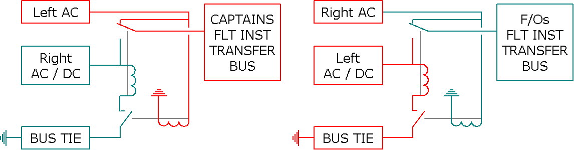
- The left main system powers the left autopilot and the Captain's Flight Instrument Transfer Bus.
- The right main system powers the right autopilot and the First Officer's Flight Instrument Transfer Bus.
- The Battery/Standby System powers the centre autopilot.
Above 200 feet, loss of a generator results in:
- Both bus tie breakers closing and the operating generator powers both left and right AC buses.
- The left main system powers the centre autopilot.
- NO LAND 3 appears on the Autoland Status Annunciator.
Below 200 feet, loss of a generator results in:
- Both bus tie breakers remaining open.
- The autopilot associated with a failed generator is unpowered.
- The flight instruments remain powered through the Flight Instrument Transfer buses.
- The Autoland continues using the remaining two autopilots.
When the autopilots are disengaged or an autopilot go-around is performed, the electrical system reverts to normal, non-isolated operation.
Flight Instrument Transfer buses
Normally, the captain's flight instruments are powered by the left main AC Bus, and the first officer's flight instruments are powered by the right main AC Bus. If the respective bus tie breakers are in AUTO, the flight instrument transfer buses transfer to the opposite main AC bus in the event power is lost to a main AC Bus.
AC Transfer buses
ETOPs fitted
Left and right AC transfer buses power items considered necessary for ETOPs flights, which are not powered by the battery/standby system. Transfer buses are normally powered by their associated main AC buses, but also can be powered by the Hydraulic Driven Generator when both AC buses are unpowered.
Electrical Load Shedding
Electrical load shedding occurs automatically to ensure power is available to critical and essential equipment, and there are three conditions which result in load shedding:
Overload Load Shedding
If the electrical loads exceed the power available, the electrical system automatically sheds AC loads by priority until the loads are within the capacity of the generators.
On the ground prior to engine start with a Centre or Left electric hydraulic pump selected ON, overload protection operates in two phases. When the APU or external power exceeds its load limit, the Galley buses trip off. There is no cockpit indication of this trip off. The Utility buses trip off if the overload continues, illuminating the Utility Bus OFF lights.
If only the Galley buses trip off, they reset automatically as soon as the respective bus tie breaker opens or when all electric hydraulic pumps are selected OFF. For example, during engine start, as the generator comes on line and its bus tie opens, the galleys connected to it automatically reset. A manual reset is required if the Utility buses also trip off. Pushing the Utility Bus Switches OFF then ON again resets the Utility buses and the Galley buses.
If a separate generator is supplying each main AC bus, only the Utility and Galley buses associated with the overloaded generator are shed
The load shedding [order] is:
- Galley buses.
- Utility buses.
- Individual equipment items powered by the main AC buses.
When an additional power source becomes available or the load decreases, the electrical system automatically restores power to the shed systems (in the reverse order).
Engine Start Load Shedding
Engine start load shedding occurs when the APU is used for both electrical and pneumatic power during engine start. This load shed trips the Utility and Galley buses, illuminating both Utility Bus OFF lights. By unloading the APU electrically, ample APU pneumatic power is assured for engine start.
When the first Engine Start Selector is moved to the GND position, both Utility and Galley buses trip off. The Utility Bus OFF lights illuminate. They reset automatically when either the generator breakers close or the engine start selector trips from GND to AUTO.
When the second Engine Start Selector is moved to GND, only the Utility and Galley buses connected to that engine trip Off.
Examples of load shedding that may be observed in the flight deck or cabin during normal operations include:
- An Electric Hydraulic Pump prior to engine start.
- Centre Tank Fuel Pumps prior to engine start.
- Utility buses during engine start.
Generator Loss Load Shedding
During takeoff or inflight, the loss of one generator causes both Utility buses and all Galley buses to trip off. As a result, both Utility Bus OFF Lights illuminate. These buses cannot be reset manually in flight. However, on the ground with one or both Thrust Levers retarded, they can be rest by pushing the Utility Bus Switches OFF then ON again. In flight, they can only be reset by re-establishing a second generator. When a second generator comes on line, the Utility and Galley buses reset automatically.
Additional loads are automatically shed if an engine is shutdown inflight. This additional load shedding partially offsets the hydraulic system requirement for additional electrical power to operate the electric hydraulic pump.
Examples of load shedding that may be observed in the flight deck or cabin during non-normal operations include:
- Utility buses after a generator or engine failure.
- Respective Centre tank fuel pump after an engine failure.
- ALL cabin indirect ceiling Lights and the forward direct ceiling Lights after an engine failure.
Arming of this load shed protection requires that the Air/Ground Logic be in the flight mode, or that the Thrust Levers both be moved into the Takeoff range.
On the ground, advancing the thrust levers into the takeoff range with the engines shut down may cause inadvertent load shedding of the utility buses to occur. Returning the thrust levers to idle, then pushing the UTILITY BUS switches OFF, then ON will reset this inadvertent load shedding.
Main DC Electrical System
- Bus Equipment - Left DC Bus
- Bus Equipment - Right DC Bus
The main DC electrical system uses two Transformer-Rectifier Units (TRUs) to produce DC power. The TRUs are powered by their respective main AC buses. On some airplanes, backup DC power is provided by a Hydraulic Driven Generator.
DC Bus Tie Breaker
During normal operations, the Left and Right TRUs (and buses) operate isolated from one another. However, if one TRU fails, the DC Bus Tie Breaker closes automatically to keep both DC buses powered. Both AC Bus Tie Switches must be in AUTO for the DC Bus Tie Breaker to close. If either switch is OFF, the DC bus tie breaker cannot close.
There are no flight deck controls for the main DC electrical system.