Landing Gear
Amendment: Air/Ground Sensing system QRH notes added.
- Boeing - Nose Gear Operation During Approach
Introduction

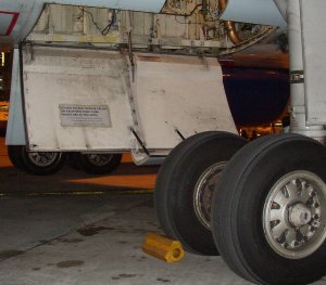
The airplane has two main landing gear and a single nose gear. The nose gear is a conventional steerable two-wheel unit. Each main gear has four wheels in tandem pairs.
Hydraulic power for retraction, extension, and steering is supplied by the Left Hydraulic system. An Alternate Extension System is also provided.
The 757-300 is equipped with a Tailskid System.
The Normal/Reserve brake systems are powered by the Right Hydraulic system. The Alternate Brakes system is powered by the Left Hydraulic system.
Antiskid protection is provided with both systems, but the autobrake system is available only through the normal system.
Accumulator Brake power is available for the normal brake system if required.
Air/Ground Sensing System
In-flight and ground operation of various airplane systems are controlled by the air/ground sensing system and the nose air/ground sensing system.
Truck Tilt Sensors
 The air/ground sensing system receives air/ground logic signals from Truck Tilt sensors located on each main landing gear. These signals are used to configure the airplane systems to the appropriate air or ground status and provide input to the following services:
Nose Gear Compressed Sensors
A nose air/ground sensing system receives air/ground logic signals from nose gear strut compression sensors. These signals are for controlling:
- Stall Warning and
- portions of the Caution and Warning system
For most functions, only one system is used. However, critical airplane function may use both systems for air/ground sensing.
As installed (SB changes allows the message to be displayed.)
An EICAS advisory message AIR/GND SYS or NOSE A/G SYS indicates that some portion of the sensing system failed. Affected equipment and systems will not operate normally and therefore takeoff is not allowed.
- One or both Thrust Reversers inoperative
- Auto Speedbrake inoperative. When deployed manually, spoiler capability is reduced.
[The ground spoiler on each wing will not deploy.] - Auto brakes inoperative.
Landing Gear Operation
The landing gear are normally controlled by the landing gear lever.
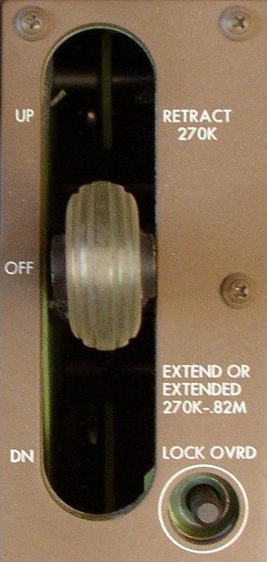
Landing Gear Lever
- UP. The Landing Gear Retraction sequence is initiated. Automatic wheel braking occurs.
- OFF. Landing Gear system is depressurised. All gear and doors are then held in the retracted/closed position by mechanical locks.
- DN. The Landing Gear Extension sequence is initiated.
Landing Gear Lever Lock
On the ground, the lever is held in the DN position by an automatic lever lock. The Lever Lock is controlled by the main gear Truck Tilt Sensors. When the gear is not tilted (airplane on the ground), the lock is engaged. The lever lock can be manually overridden by pushing and holding the landing gear lever LOCK OVRD switch. In flight, the lever lock is automatically released through air/ground sensing.
Landing Gear Retraction
 After takeoff, both main gear tilt, releasing the lever lock.
When the landing gear lever is positioned to UP, the landing gear begins to retract. The landing gear doors open and the main gear wheels tilt to the retract position. Automatic wheel braking occurs during gear retraction. The GEAR and DOORS lights illuminate as the landing gear retracts into the wheel wells. After retraction, the landing gear are held up by uplocks. The GEAR and DOORS lights extinguish. The landing gear lever is placed in the OFF position to depressurise the landing gear system.
The GEAR light remains illuminated and the EICAS caution message GEAR DISAGREE display if any gear is not up and locked up after the normal transit time. The affected gear's, gear down light, remains illuminated if the gear never unlocked from the down position. The DOORS light remains illuminated and the EICAS advisory message GEAR DOORS display if any hydraulically actuated door is not closed after normal transit time.
Landing Gear Extension
When the landing gear lever is moved to DN, the landing gear doors open, the gear are unlocked, and the GEAR and DOORS lights illuminate.
The gear are hydraulically powered to the down and locked position. The downlocks are powered to the locked position, all hydraulically actuated gear doors close, and the main gear trucks hydraulically tilt to the flight position. When all gear are down and locked, the gear down lights illuminate and the GEAR and DOORS lights extinguish.
The GEAR light remains illuminated and the EICAS caution message GEAR DISAGREE display if any gear is not locked down after the normal transit time. The extinguished gear down light indicates the affected gear. The DOORS light remains illuminated and the EICAS advisory message GEAR DOORS display if any hydraulically actuated door is not closed after the normal transit time.
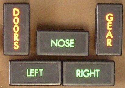
Landing Gear Down Indication
Main gear down locking is provided by a side brace and a drag brace. The LEFT and RIGHT Gear Down Lights come on when both lock-links attached to the side struts for each gear are locked. The NOSE Gear Down Light comes on when the nose gear is down and locked.
Landing Gear Alternate Extension
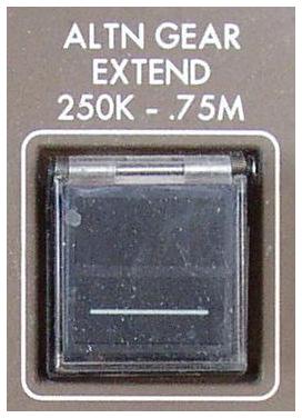 The alternate landing gear extension system uses a dedicated DC-powered (Hot Battery Bus) electric hydraulic pump to extend the landing gear. Fluid within the supply line to the pump is sufficient for alternate gear extension operation. This fluid is isolated from the Left Hydraulic system. Selecting the ALTN GEAR EXTEND switch releases all door and gear uplocks. Gravity and air loads force the landing gear free-fall to the down and locked position. The time for operation is approximately 10 seconds.
When all gear are down and locked, the gear down lights illuminate and the GEAR light extinguishes. During alternate extension, the DOORS light remains illuminated and the EICAS advisory message GEAR DOORS display because all the hydraulically powered gear doors remain open with or without Left Hydraulic System pressure. The open doors have adequate ground clearance for landing.
Nose Wheel Steering
Nose wheel steering is powered by the ‘gear down’ lines of the Left Hydraulic system.
Primary steering control is provided by the left sidewall nose wheel steering tiller. Limited steering control is available through the rudder pedals when the nose gear is in contact with the runway. The tiller can turn the nose wheel up to 65 degrees in either direction by rotating the tiller 360 degrees in the required direction. A pointer on the tiller assembly shows tiller position relative to the neutral setting. The rudder pedals can be used to turn the nose wheels up to seven degrees in either direction. Tiller inputs override rudder pedal inputs.
The Power Transfer Unit (PTU) can power the nosewheel steering system in the event of a Left Engine failure or low hydraulic pressure from the left engine hydraulic pump. The PTU augments the Left Hydraulic System electric pump to supply pressure to the nose wheel steering system.
Turn Radius
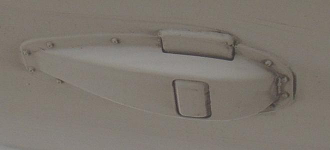
Tailskid (757-300)
 The airplane is equipped with a tailskid system to compensate for the reduced tail clearance. The tailskid - in the form of a retractable, crushable cartridge - extends for takeoff and landing and retracts during flight. It helps to protect the pressurised part of the airplane from contact with the runway. The tailskid is powered by the Left Hydraulic System and uses the main landing gear actuation system. Operation is automatic with Landing Gear selection.
The tailskid does not extend when Alternate Gear extension is used.
The TAILSKID light illuminates and the EICAS advisory message TAILSKID is displayed when the tailskid position disagrees with the landing gear lever.
A red pop-out indicator on the bottom of the shock absorber is visible from the ground and would show if the drag shoe has contacted the runway. If the indicator is extended, maintenance personnel check the serviceability of the cartridge using two inspection holes.
- See also: Warning Systems - Tailstrike Indication
Tail Scrape Damage Limiter
 AMM
Some 757-200 airplanes are fitted with a Tail Scrape Damage Limiter (TSDL). The TSDL is only designed to absorb some of the impact of a tail strike and thus reduce internal damage to the aircraft. If any wear or damage is evident, then a full inspection must be completed.
AMM
Some 757-200 airplanes are fitted with a Tail Scrape Damage Limiter (TSDL). The TSDL is only designed to absorb some of the impact of a tail strike and thus reduce internal damage to the aircraft. If any wear or damage is evident, then a full inspection must be completed.