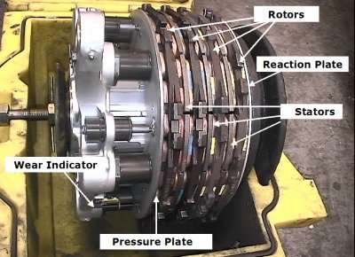
Brake Units
Amendment: Notes relating to Brake Wear Indicators included.
- 757-200 - Steel brakes are fitted.
- 757-300 - Carbon brakes are fitted.
Brake Temperature Indication
As installed
Wheel brake temperatures are displayed on the EICAS status page. Numerical values related to wheel brake temperature are displayed for each main gear brake. Brake temperature values range from 0 to 9, corresponding to a brake temperature range of 100 to 650°C (212 to 1202°F). The values are not instantaneous readings of wheel brake conditions and tend to increase for 10 to 15 minutes after the brakes are used.
Initial range values of 0 to 2 are cyan numbers in a cyan box. For normal range values of 3 and 4, the number is cyan and the box is white. If two brake values are within the normal range, the highest value or the first brake to reach the highest value is surrounded by the white box. Values in the high range of 5 to 9 have a white number and box. The BRAKE TEMP light illuminates for values of 5 and above.
Brake Unit Faults
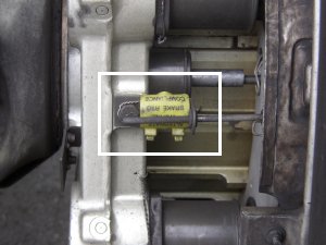
Brake Wear Indicators
 AMM
With the brakes applied, if the wear indicator pin does not extend out of the grommet on the guide bracket, then the brake must be replaced.
AMM
With the brakes applied, if the wear indicator pin does not extend out of the grommet on the guide bracket, then the brake must be replaced.
Note: Some BF Goodrich brakes have plastic tags that show "ALTERNATE WORN BRAKE RTO COMPLIANCE". These tags are near the brake wear pins. The tags are put on brakes that comply with FAA worn brake requirements and can be ignored.
Note: There are actually 2 Brake Wear Indicator pins per unit, but the inner set are difficult to see at night and can be disregarded for all intents and purposes.
The following information is from the Flight Crew Training Manual
Taxi Speed and Braking
Taxi speed should be closely monitored during taxi out, particularly when the active runway is some distance from the departure gate. Normal taxi speed is approximately 20 knots, adjusted for conditions. On long straight taxi routes, speeds up to 30 knots are acceptable, however at speeds greater than 20 knots use caution when using the nose wheel steering tiller to avoid over controlling the nose wheels. When approaching a turn, speed should be slowed to an appropriate speed for conditions. On a dry surface, use approximately 10 knots for turn angles greater than those typically required for high speed runway turnoffs.
Note: High taxi speed combined with heavy gross weight and along taxi distance can result in tyre sidewall overheating
Heat Generation
As severe as the effects of high centrifugal forces are, heat has a more detrimental effect. Heavy loads and high speeds cause heat generation in aircraft tyres to exceed that of all other tyres.
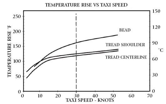
The vertical dotted line at 30 knots indicates the recommended maximum taxi speed.
Even when an aircraft tyre is properly inflated and operated at moderate taxi speeds, the heat generation will always exceed the heat dissipated. The farther the taxi distance, the hotter the tyres will be at the start of the take-off.
When the airplane is equipped with steel brakes, avoid prolonged brake application to control taxi speed as this causes high brake temperatures and increased wear of brakes. If taxi speed is too high, reduce speed with a steady brake application and then release the brakes to allow them to cool. Braking to approximately 10 knots and subsequent release of the brakes results in less heat build-up in the tyres and brakes than when the brakes are constantly applied.
Under normal conditions, differential braking and braking while turning should be avoided. Allow for decreased braking effectiveness on slippery surfaces. Avoid following other aircraft too closely. Jet blast is a major cause of foreign object damage.
Carbon Brake Life
Brake wear is primarily dependent upon the number of brake applications. For example, one firm brake application causes less wear than several light applications. Continuous light applications of the brakes to keep the airplane from accelerating over a long period of time (riding the brakes) to maintain a constant taxi speed produces more wear than proper brake application. During taxi, proper braking should involve a steady application of the brakes to decelerate the airplane. Release the brakes as lower speed is achieved. After the airplane accelerates, repeat the braking sequence.
Antiskid Inoperative
With antiskid inoperative, tyre damage or blowouts can occur if moderate to heavy braking is used. With this condition, it is recommended that taxi speed be adjusted to allow for very light braking.
Wheel Brakes
Braking force is proportional to the force of the tyres on the runway and the coefficient of friction between the tyres and the runway. The contact area normally changes little during the braking cycle. The perpendicular force comes from airplane weight and any downward aerodynamic force such as speedbrakes.
The coefficient of friction depends on the tyre condition and runway surface, (eg concrete, asphalt, dry, wet or icy).
Automatic Brakes
Boeing recommends that whenever runway limited, using higher than normal approach speeds, landing on slippery runways or landing in a crosswind, the autobrake system be used.
For normal operation of the autobrake system select a deceleration setting.
Settings include:
MAX AUTO: Used when minimum stopping distance is required. Deceleration rate is less than that produced by full manual braking
3 or 4: Should be used for wet or slippery runways or when landing rollout distance is limited
1 or 2: These settings provide a moderate deceleration effect suitable for all routine operations.
Note: Autobrakes 2 or greater results in a continuous brake application, which can increase carbon brake life.
Flight crew/airline experience with airplane characteristics relative to the various runway conditions routinely encountered provide initial guidance as to the desirable level of deceleration selected.
Immediate initiation of reverse thrust at main gear touchdown and full reverse thrust allow the autobrake system to reduce brake pressure to the minimum level. Since the autobrake system senses deceleration and modulates brake pressure accordingly, the proper application of reverse thrust results in reduced braking for a large portion of the landing roll.
The importance of establishing the desired reverse thrust level as soon as possible after touchdown cannot be overemphasised. This minimises brake temperatures and tyre and brake wear and reduces stopping distance on very slippery runways.
The use of minimum reverse thrust almost doubles the brake energy requirements and can result in brake temperatures much higher than normal.
[Flight Crew Training Manual]
Deactivated. The brake unit is serviceable, but a fault has been found in the control system and the control unit for that wheel brake unit has been deactivated. Automatic gear retract braking is serviceable. Penalty 1,000 kg.