Electrics - Battery & Standby Power System 
- Supplementary Procedures - Battery Start Procedure
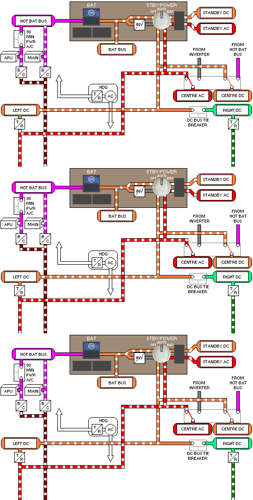
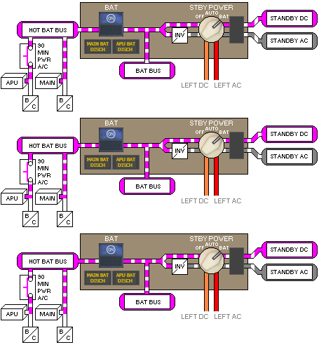
The Battery/Standby Power System can supply DC and AC power to selected flight instruments, communications and navigation systems, and other critical systems, if there are main AC and DC electrical power system failures.
The Battery/Standby Power System comprises the following Buses:
If all generator power is lost, these are the only buses that can be powered by the batteries.
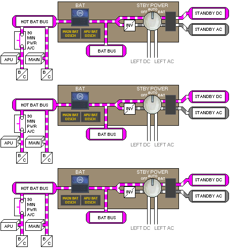
- See: Battery Schematic
- See: Bus Equipment List
Batteries
There are two batteries on the airplane, the APU Battery and the Main Battery. The APU battery is used for starting and operating the APU. It can also be paralleled with the main battery to provide backup power for the standby power system. There is no direct cockpit control for the APU battery.

The main battery directly supplies the Hot Battery Bus. Normally, left main DC power supplies Battery Bus power. When there is no left main DC power, or when the Standby Power Selector Switch is in the BAT position, the main battery supplies power through the Battery Switch to the Battery Bus.
Each battery has a charger powered from the Ground Service Bus.
If the STBY POWER switch is set to BAT position, the charger is disconnected from the Ground Service Bus.
Airplanes With 90-minute Standby Power
The main and APU batteries are paralleled if power is lost at the Left DC bus. This provides a 90 minute standby power source.
Hot Battery Bus
- Bus Equipment - Hot Battery Bus
The hot battery bus provides power to items that must be continuously powered, such as the Clock's time reference.
Prior to establishing electrical power, the Main Battery powers the Hot Battery Bus. After establishing electrical power, the Main Battery charger powers the Hot Battery Bus.
Battery Bus
- Bus Equipment - Battery Bus
Prior to establishing electrical power, when the Battery Switch is ON, the Main Battery powers the Battery Bus.
After establishing electrical power, the Left DC system powers the Battery Bus, and the main battery provides a backup source of power.
 The MAIN BAT DISCH light illuminates when the Main Battery is discharging. If EICAS is powered, the advisory message MAIN BAT DISCH also displays.
The Battery OFF light illuminates and the EICAS advisory message BATTERY OFF displays if the battery switch is OFF after electrical power is established.
Standby DC Bus
- Bus Equipment - Standby DC Bus
 Prior to establishing electrical power, when the Battery Switch is ON and the Standby Power Selector is in AUTO, the Main Battery and the APU Battery are paralleled to power the Standby DC bus. The MAIN BAT DISCH light and the APU BAT DISCH light illuminate when the main battery and APU battery are discharging.
After establishing electrical power, the Left DC system powers the Standby DC bus and the Main Battery and APU Battery provide a backup source of power.
When the Standby Power Selector is in BAT, the main battery and the APU battery are paralleled to power the Standby DC Bus.
The Standby Bus OFF light illuminates and the EICAS advisory message STANDBY BUS OFF displays if the Standby DC bus is unpowered.
Standby AC Bus
- Bus Equipment - Standby AC Bus
Prior to establishing electrical power, when the Battery Switch is ON and the Standby Power Selector is in AUTO, the Main Battery and the APU Battery parallel to power the Standby Inverter which provides AC power to the Standby AC bus.
After establishing electrical power, the Left AC system powers the Standby AC Bus and the Main Battery, APU Battery and Standby Inverter provide a backup source of power.
When the standby power selector is in BAT, the Main Battery, APU Battery and Standby Inverter power the Standby AC Bus.
The Standby Bus OFF light illuminates and the EICAS advisory message STANDBY BUS OFF displays if the Standby AC Bus is unpowered.
Standby Power Selector
OFF
In the OFF position, the selector cuts off all sources of power to the Standby DC and Standby AC Buses.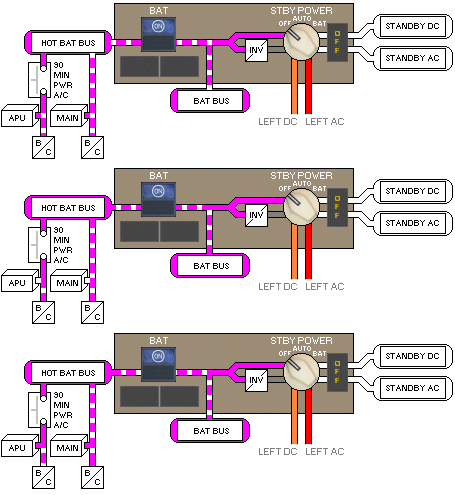
Boeing In flight, loss of Standby DC power is sensed as a double engine failure and unlocks the RAT. If the Standby Power Selector is placed OFF (in flight) on the 757, full RAT deployment could be expected due to the spring extension mechanism.
AUTO
The Standby Power Selector affects the power going to the Standby DC and Standby AC buses. With the selector in the AUTO position, left main DC and AC power have priority in supplying the two Standby Buses.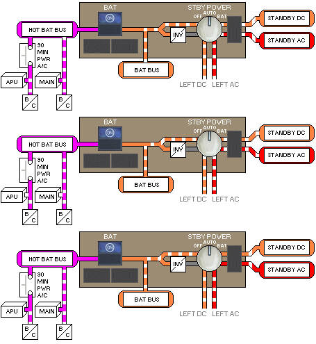
When the Battery Switch is ON, the AUTO position also permits the main battery, APU battery and battery chargers to act as backup power sources for the two buses.
- BAT
Selecting the BAT position cuts off main AC and DC power to the standby system. The only power remaining for the standby system is battery power. In this case even the battery chargers are cut off.With the Battery Switch ON, the battery supplies Standby DC and Standby AC through the Static Inverter.
