Engines - General (RR) 
Amendments: Engine Speed card.
- QRH - DUAL ENGINE FAILURE
- QRH - ENGINE FIRE or SEVERE DAMAGE or SEPARATION
- QRH - ENGINE LIMIT or SURGE or STALL
- Boeing - Dual Engine Failure
- Boeing - Flight Crew Considerations for Engine In-Flight Shutdown
- Boeing - Flight Crew Considerations for Engine Surge
- Boeing - Engine Operating Limitations
Introduction
- The 757-200 airplane is powered by two Rolls-Royce RB211-535E4 engines rated at 40,100 pounds of takeoff thrust each.
- The 757-300 airplane is powered by two Rolls-Royce RB211-535E4-B engines rated at 42,700 pounds of takeoff thrust each.
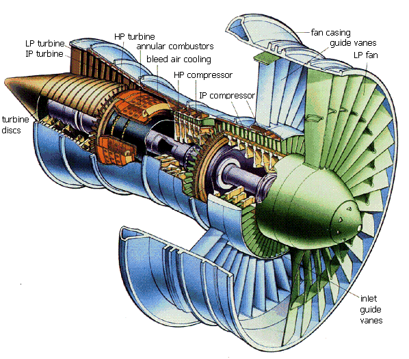
image source: www.eng.uct.ac.za/~victor/electric/GasTurbine.htm
The engines are three-rotor axial flow turbofans of high compression and bypass ratio. The N1 rotor consists of the Fan and a Low Pressure turbine section on a common shaft. The N2 rotor consists of an Intermediate Pressure compressor section and an Intermediate Pressure turbine section on a common shaft. The N3 rotor consists of a High Pressure compressor section and a High Pressure turbine section on a common shaft. The N1, N2 and N3 rotors are mechanically independent. The N3 rotor drives the engine accessory gearbox.
Accessory Gearbox
The Engine Accessory gearbox drives the:
- Pressure and Scavenge Oil pumps
- Dedicated generator for EEC and Bleed Air Valves
- HP tachometer (N3 rpm)
The Air-Driven Starter connects to the N3 rotor through the accessory gearbox.
Each engine has individual flight deck controls. Thrust is set by positioning the Thrust Levers, [either] automatically by the autothrottle system or manually by the flight crew.
Each engine is controlled by an Electronic Engine Controller (EEC). The EECs monitor autothrottle and flight crew inputs through the Thrust Levers to automatically control the engines.
The engine incorporates automatic surge bleed valves to ensure good starting characteristics plus surge and stall free operation throughout the airplane's flight envelope.
Engine Indications are displayed on the Engine Indication and Crew Alerting System (EICAS) display.
Engine Speed Card
- Equipment cooling system
- APU fire extinguishing
- Fuel boost pumps
- Power Transfer Unit
- Ram Air Turbine
- Angle of Attack probe heat
- Pitot-Static probe anti-icing
- Total Air Temperature probe heat
- Flight Management Computers
- Electronic Engine Control
- Engine start system
- Air cooling pack system.
Bleed Valve Control Unit
AMM To keep a stable airflow through the compressor section during certain transient and steady running conditions, a percentage of air is vented from the intermediate pressure (IP) and high pressure (HP) compressors. This is achieved through solenoid operated bleed valves controlled by an electronic Bleed Valve Control Unit (BVCU). An integral part of the BVCU also provides automatic control of the bleed valves in the event of abnormal deceleration of the engine at high power settings, as may be caused by a bird strike or surge.
Note: These bleed valves are separate to the normal pneumatic system engine bleed air valves