Engines - Controls (RR)
Amendment: EEC and ELC Failures and B757-300 EGT Exceedances.
Forward Thrust Levers
Forward Thrust Levers are provided to control engine forward thrust requirements from idle to maximum power.
Reverse Thrust Levers
- See: Thrust Reverse
Thrust Management Computer
- See also: Automatic Flight - Autothrottle
The Thrust Management Computer calculates a reference EPR based on existing pressure altitude and ambient temperature data from the air data system for the following modes:
- TO - takeoff
- D-TO - Assumed Temperature Takeoff
- CLB - Climb
- CLB 1 - Climb One
- CLB 2 - Climb Two
- CRZ - Cruise.
- CON - Continuous.
- GA - Go-Around
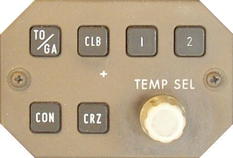 These modes can be selected with the Thrust Mode Select Panel (TMSP). The inner Thrust Reference Set control on the EICAS control panel must be pushed in for the Thrust Reference modes to be displayed on EICAS. The selected Thrust Reference mode is displayed above the EPR indicators. The digital Reference EPR is displayed adjacent to the mode display. When the EPR bug is green, it is positioned on the EPR scale at the same value as the digital reference EPR.
The Thrust Mode Select Switches provide the capability of selecting different thrust modes for each phase of flight:
The TO/GA switch is used to select takeoff thrust on the ground and go-around thrust in-flight.
The 1 and 2 switches are used to select a Reduced Climb Thrust. When reduced takeoff thrust rating one or two is selected, this automatically pre-selects the associated reduced climb one or two. The CLB switch is used to select climb thrust in-flight. If reduced climb thrust one or two was pre-selected, pushing the climb switch in-flight selects CLB 1 or CLB 2.
The CON switch is used to select Maximum Continuous thrust in-flight.
The CRZ switch is used to select Cruise thrust in-flight.
The Assumed Temperature Selector on the TMSP or the CDU TAKEOFF REF page is used to set assumed temperatures when reduced takeoff thrust is desired. The assumed temperature is displayed above the Thrust Reference Mode.
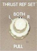 To manually set reference EPR values the Thrust Reference Set Control is pulled out, MAN appears as the thrust mode annunciation and the EPR bug slews to 1.55. Manual reference EPR values can then be set by rotating the inner control. The outer control of the Thrust Reference Set Control is used to select the desired EPR indicator(s) for manual EPR display. The autothrottles do not respond to manually set Reference EPR values. When the inner control is pulled out, the autothrottles remain in the active TMC mode. The TMSP remains operable and the autothrottles respond to TMSP mode changes, but selected Thrust Reference Mode displays are inhibited.
When the AFDS VNAV mode is engaged, the EPR bug may be magenta. When the EPR bug is magenta, it is positioned at a nominal target EPR by the FMC, which may not correlate with the digital reference EPR. In VNAV, the FMC controls Thrust Mode selection automatically to meet thrust requirements for the active vertical mode of operation. The FMC does not have the capability to select reduced climb thrust values; these values must be selected manually with the 1 or 2 Thrust Reference Mode Select switches.
The Thrust Reference mode, Reference EPR and Target EPR indication are not displayed when the reversers are fully deployed.
Assumed Temperature Takeoff
When the Assumed Temperature Selector on the TMSP is initially rotated clockwise, a reference temperature is displayed on EICAS. This temperature also appears on the FMC CDU TAKEOFF REF page as THRUST (PEGASUS). Further clockwise rotation of the selector increases the assumed temperature by 1 degree centigrade per click. The reduced thrust annunciation of D-TO appears when the assumed temperature selected is above ambient. If the ambient temperature is greater than the initially displayed reference temperature, D-TO and reduced thrust occur when the assumed temperature selected exceeds ambient.
Counter clockwise rotation of the selector reduces the assumed temperature by one degree centigrade per click.
Assumed temperature takeoff thrust is limited to a 25% reduction of maximum takeoff thrust or selected climb thrust, whichever is the greater thrust value. When the limit is reached, further clockwise rotation of the selector or changing the value entered in the CDU TAKEOFF REF page (PEGASUS) does not change the displayed assumed temperature or reference thrust value.
Reduced Climb Thrust
Two levels of reduced climb thrust are available with the 1 and 2 mode switches on the Thrust Mode Select Panel. Climb 1 is approximately 94% of climb thrust and climb 2 is approximately 88% of climb thrust.
Climb 1 or 2 can be pre-selected in conjunction with the TO, D-TO, CON and CRZ Thrust Reference modes. Reduced climb thrust is available throughout the airplanes operational envelope.
Electronic Engine Control
The thrust system comprises a hydro-mechanical engine Fuel Control Unit with an Electronic Engine Control (EEC) unit mounted on each engine. Each engine EEC is powered by dual dedicated generators.
 The EEC sets thrust by controlling EPR based on thrust lever position. EPR is commanded by positioning the thrust levers either automatically with the autothrottles, or manually by the flight crew. Both engines may be operated by conventional hydro mechanical control by disengaging the EECs.
The EEC continuously computes the maximum limits for thrust. Maximum rated thrust is available in any phase of flight by moving the thrust levers to the full forward positions. Maximum EPR represents the maximum rated thrust available from the engine.
These values are displayed by the position of the amber radial on the EPR display. If the EEC fails or is turned off, these values are computed by the TMC and displayed in the same manner. If the TMC fails, the maximum limits are blank.
During normal EEC operation, each EEC provides a trim input to its associated hydro-mechanical fuel controller to drive the engine to an EEC computed Command Thrust Level. The EEC computes this EPR as a percentage of its maximum limit computation. The percentage is varied with thrust lever position, such that at full throttle, the percentage is 100%. During rapid throttle lever movements, the difference between the engines actual EPR and the EECs commanded EPR is displayed as the Command Sector on the EICAS EPR display. The engine is controlled by its hydro mechanical fuel controls at low power operating conditions.
The EEC INOP light illuminates and the L/R EEC OFF EICAS caution message displays to indicate the EEC is turned off or a failure is detected in the system. When a failure is detected the EEC trim motor will hold the current trim level until the unit is turned off. When the EEC is turned off and the thrust lever is positioned full forward, a L/R EEC OFF caution message is displayed.
Caution: The thrust lever should be retarded to a mid position before turning the EEC off to prevent a possible engine overboost.
Turning the EEC ON at high power is permissible. This action will result in an immediate thrust down trim as the EEC assumes control of the engine. Immediate movement of the thrust lever to restore thrust is acceptable.
Engine Limiter Control
 The thrust control system also includes electronic ELC unit. If required, both engines may be operated conventionally by manually disengaging the ELCs.
Each engine ELC is powered by dual dedicated generators
The ELC INOP light illuminates and the L/R ENG LIMITER EICAS advisory message displays to indicate the ELC is turned off or a failure is detected in the system. When a failure is detected the ELC will hold the current trim level until the unit is turned off.
Caution: When operating at or near any limit, the thrust should be reduced before turning the ELC off; otherwise a momentary overspeed condition could develop.
EEC and ELC Malfunctions during Engine Start
If the engine starter cutout functioned normally, attempt to reset the system by cycling the EEC switch whilst the engine is operating. This can be attempted several times if necessary. If the system resets, then normal operation may continue, but the [event] should be recorded in the technical log.
If the system cannot be reset then a thrust shortfall on takeoff may result, and engineering action is required before despatch.
If the engine starter did not cut out normally, the EEC fault is indicative of a dedicated generator failure. Engineering action is required before despatch.
[Amplified Normal Procedures]Overboost/Overspeed Protection
The EEC also provides N1, N2 and N3 red line overboost protection. If N1, N2 or N3 approaches overboost, the EEC commands reduced fuel flow.
If engine limit protection is not available, advancing the thrust levers full forward should be considered only during emergency situations when all other available actions have been taken and terrain contact is imminent.
The ELC provides N1 limit protection only.
Note: Engines PRE SB 71-8093 also monitor EGT.
Idle Selection
There are two engine idle speeds:
Minimum Idle. Minimum idle is a lower thrust than approach idle and is selected for all ground operation and for all phases of flight except approach and landing.
Approach Idle. Approach Idle is selected automatically whenever this higher idle setting is required for proper system operation.
During approach and landing when the Landing Gear is down or the Flaps are set to 25 or 30, the idle speed setting increases from minimum to approach. Approach idle setting is maintained until 5 seconds after touchdown to facilitate a faster acceleration for go-around or reverse thrust operation. After the 5 second delay the approach idle speed reverts back to minimum idle to help minimise the landing roll. In-flight when engine anti-ice is turned on, the idle speed setting also automatically increases to the approach setting to maintain higher idle speeds during icing conditions.
The EEC selects these idle speeds automatically.