Engines - EICAS (RR)
Amendment: B757-300 EGT Exceedances.
Introduction
The Engine Indication and Crew Alerting System (EICAS) consolidates engine and selected subsystem indications as well as crew alerting functions. The system includes two colour cathode ray tubes (CRTs), two computers and a control panel.
A Computer Selector determines which computer controls EICAS CRTs. When the selector is in the AUTO position the Left computer is used. If the Left computer fails, control switches to the right computer. When the L position is selected only the left computer can control the CRTs. When the selector is in the R position only the right computer can control the CRTs. This can be used to correct display faults not automatically detected by the system.
The brightness controls are used to adjust the brightness level of the CRTs. The inner knob controls the upper display brightness and the outer knob controls the lower display brightness. Turning either knob adjusts the brightness level of both displays by the same amount. To adjust the brightness level of a single display, one knob must be held stationary while the other knob is adjusted.
- For information on EICAS-related warning systems, see Warning Systems - EICAS
Engine Indications
Primary and secondary engine indications are provided. Engine indications are displayed on the EICAS display. In addition, annunciator lights and a liquid crystal Standby Engine Indicator are provided to monitor engine operation.
Primary Engine Indications
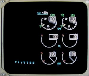
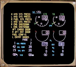
EPR, N1 and EGT are the primary engine indications [and] are displayed on the upper EICAS display.
Warning, caution and advisory messages, which indicate system faults, also appear on the upper CRT. This combination of primary engine indications and crew alerting messages is called the EICAS Primary Display.
EICAS records RPM and EGT exceedance conditions in an auto event memory. The maximum exceedance value is displayed in smaller white numbers below the actual value counter.
- Boeing Fleet Newsletter - B757-300 EGT Exceedances
Secondary Engine Indications
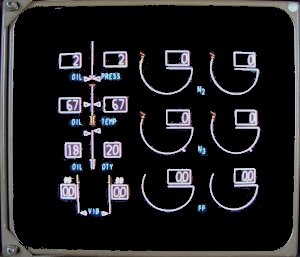
 N2, N3, Fuel Flow, Oil Pressure, Oil Temperature, Oil Quantity and Engine Vibration are secondary engine indications [and] are displayed on the lower EICAS display. The secondary indications can be displayed by pushing the Engine Display Switch (the ENGINE switch on the EICAS control panel). The secondary engine indications are automatically displayed when:
- The displays initially receive electrical power or
- A secondary engine parameter is exceeded.
When the Status Display Switch is pushed, the lower EICAS display changes to show the Status Page for other pre-flight checks, typically including hydraulic contents, APU EGT and Oxygen contents.
Normal Display Format
Primary engine indications and the N2, N3 and Fuel Flow indications are digital readouts and round dial/moving pointer indications. The digital readouts display numerical values while the moving pointers indicate relative value.
Oil Pressure, Oil Temperature, Oil Quantity and Engine Vibration indications are both digital readouts and vertical indication/moving pointers. All digital readouts are enclosed by boxes. The dial and vertical indications display the normal operating range, caution range and operating limits (as applicable).
Normal operating range is displayed on a dial or vertical indication in white.
Non-Normal Indications
The Oil Temperature and Oil Pressure vertical indications have caution ranges displayed by amber bands. If oil temperature or oil pressure reaches the caution range, the digital readout, digital readout box, and pointer all change colour to amber.
N1, EGT, N2, N3, Oil Pressure, and Oil Temperature indications have operating limits indicated by red lines. If one of these indications reaches the red line, the digital readout, box, and pointer change colour to red for that indication.
The EGT indication has a maximum continuous limit represented by an amber band. If EGT reaches the maximum continuous limit, the digital indication, box, pointer, and dial all change colour to amber. EGT, N1, N2 and N3 indications are inhibited from changing to amber during takeoff or go-around for five minutes.
The red line limits for these parameters are not inhibited. The EGT indication has a maximum takeoff limit displayed by a red line. If EGT reaches the maximum takeoff limit, the digital indication, box, pointer and dial, all change colour to red.
The maximum EPR limit is indicated by an amber line at the top of the EPR dial. The EPR indication does not change colour when maximum EPR is reached. The reference/target EPR indication displays the FMS reference or target EPR. The commanded EPR indication displays the EEC calculated EPR commanded by thrust lever position.
Automatic Call-up
EICAS Incorporates an automatic call-up feature that displays information automatically when necessary.
If the EICAS Secondary Display is not in view and if any N2 or N3 RPM reaches the amber Band or Red line limit, both engine N2 or N3 Indications are automatically displayed. Should oil Pressure or Temperature reach the Amber Band or Red line limit, or should the oil quantity decrease into the low quantity band, all oil parameters for both engines are automatically displayed. If the engine vibration reaches the amber band, both engine vibration displays appear on EICAS. If the status page is displayed when a secondary engine exceedance occurs, the status page is automatically replaced by the engine exceedance parameters. If status is selected after a secondary exceedance has occurred, the status page is displayed and the engine exceedance appears on the upper CRT in a partial, compacted mode.
EICAS records RPM and EGT exceedance conditions in an auto event memory. The maximum exceedance value is displayed in smaller white numbers below the actual value counter.
Special Condition Annunciations
During start, a red Maximum Start EGT radial appears at 570°C on the respective EGT display. This EGT limit remains in view until the engine start is completed.
The N1 parameter displays a green TAI annunciation when the engine anti-ice is on.
- See also: Engine Start
Compact Display Format
 In compact format, primary and secondary engine indications are combined on the same display. The EPR and N1 displays are the same as the normal displays. All other indications change to digital readouts only. If an amber or red line parameter for a digital indication is exceeded, the digital indication changes colour to amber or red (as does the box that appears around an EGT indication).
Primary and secondary engine indications are displayed on EICAS in compact format whenever a CRT fails.
Engine Secondary Data Cue
 A series of blue 'v's are visible on the lower left corner of the upper EICAS CRT any time engine data is displayed on the lower EICAS CRT. If for some reason the engine data is not visible, the Status Display Switch may be used to allow the engine data to come up partially compacted on the upper EICAS CRT display.
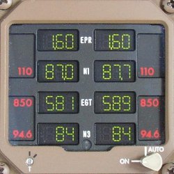
Standby Engine Indicator (SEI)
- display is blank with AC power on the airplane and EICAS operative.
- standby engine indications in view when:
- AC power is lost (EPR not displayed).
- Either CRT failed and Status selected on the ground.
- EICAS (both computers) failed.
Engine Pressure Ratio
 Engine Pressure Ratio (EPR) is the primary thrust parameter used for monitoring and setting power.
EPR is directly related to engine gross thrust. The EPR indicating system uses the ratio of pressure signals from LP compressor cold (PF) exhaust stream, and engine air intake pressure (P1) to provide an indication of engine thrust in flight compartment. The P1 probe is secured at the top centre position of the inner cowling, protrudes into the air intake and senses air inlet pressure. The probe is protected from ice formation by an electrically heated system.
Annunciations associated with EPR are:
- Maximum EPR. The Maximum EPR is the maximum certified thrust limit for all phases of flight and varies with existing ambient conditions. The maximum EPR is indicated by dual amber radials on the periphery of the EPR indicator. This value is acquired from the EEC or the TMC when the EEC is OFF or INOP. With the EEC ON, the thrust levers can be moved to the forward stop and the engines will not exceed the displayed maximum EPR.
- Thrust Reference Mode
- Reference/Target EPR indication
- Reference EPR
- Assumed Temperature
Thrust Reverser Indication. Thrust Reverser Indication (REV) is displayed above the EPR indicator when the reverser is activated. The annunciation is amber when the reverser is unlocked or in transit. When the reverser is fully deployed, the annunciation changes colour to green and the forward thrust reference displays are inhibited.
Command Thrust Level. The Command Thrust Level is a display of thrust lever position and appears as an extension of the EPR pointer when the engine is stabilised. A change in thrust lever position moves the command thrust level and displays the commanded thrust on the EPR indicator. This allows for precise thrust control.
Commanded EPR Sector. The Command EPR Sector is a display of the momentary difference between the command thrust level and existing EPR and appears as a white band on the EPR indicator. As the engine accelerates or decelerates to the command thrust level the command EPR sector is erased. This allows for monitoring of engine acceleration and deceleration.