Engines - Start (RR) 
- QRH - ABORTED ENGINE START
- QRH - DUAL ENGINE FAILURE
- Supplementary Procedures - Engine Crossbleed and Ground Pneumatic Start
- Supplementary Procedures - Battery Start Procedure
- Boeing - Dual Engine Failure
- Boeing - Flight Deck Noise with Phase 5 Combustor Engines
- Boeing - Fuel Odour After Engine Start
Air from the Pneumatic duct is used to power the air driven starter, which is connected to the N3 rotor. The starter air source may be from a ground cart, APU or the other running engine.
The ENG START selectors control the start valves. Ignition and fuel flow are controlled through the FUEL CONTROL Switches.
A maximum start limit line (red) at 570° is displayed on the EGT indication when the Fuel Control switch is moved to CUT OFF. It remains displayed after the Fuel Control Switch is moved to RUN until the engine is stabilised at idle. The EGT indication changes colour to red if the EGT start limit is reached during starting.
Engine Start
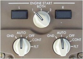
Pushing in and rotating the engine start selector to the GND position, opens the start valve, engages the air driven starter to the N3 rotor and closes the Engine Bleed Air Valve if it is open. The VALVE light illuminates and the EICAS advisory message L/R ENG STARTER displays to indicate the start valve failed to open.
As N3 rotation accelerates to Maximum Motoring rpm or 25% N3, the Fuel Control Switch is positioned to RUN or RICH. Maximum motoring speed is reached when acceleration is less than approximately 1% in 5 seconds.
During start, minimum N3 for selecting RUN is indicated by a magenta Fuel On Command Bug at 25% N3.
The Fuel Control Switch opens the Spar Valve and Engine Fuel Valve allowing the fuel to flow to the fuel control unit and activates the selected ignition.
The ignition selector may be used to select either 1 or 2 or BOTH ignitor(s). Normally, only one igniter is used for ground start while both igniters are used for in-flight starts.
At approximately 50% N3, the engine start selector automatically moves to the AUTO position. The starter automatically cuts out and the start valve closes stopping the flow of air to the starter. This allows the engine bleed valve to return to a position that agrees with the engine bleed air switch.
After starter cutout, the engine will continue to accelerate until it reaches Idle RPM. During this time, any engine bleed air extraction prior to reaching idle RPM may cause slow acceleration, a stall or a hung start. N3 RPM should be stabilised before initiating the second engine start, selecting Air Conditioning packs on, or accomplishing the After Start Procedure.
If the start valve fails to close automatically at 50% N3, the corresponding valve light will illuminate and the EICAS caution message L/R STARTER CUTOUT will display. The engine start selector must be manually moved to the AUTO or OFF position to terminate starter operation.
The RUN position is normally used for start. The RICH position is used for cold engine starts.
Starter Operation
Continuous operation of the starter must be limited in accordance with the following starter duty cycles:
Normal Duty Cycle
- Up to 2 minutes continuous operation then run down to zero N3, followed by:
- Up to 2 minutes continuous operation then run down to zero N3, followed by:
- Up to 2 minutes continuous operation then run down to zero N3 and allow to cool for 15 minutes.
Extended Duty Cycle
- Up to 4 minutes continuous operation followed by 15 minutes wait.
Re-engagement Speed
- 0% N3 Recommended
- 0-20% N3 Normal
Re-engagement is not recommended above 20% N3 except in case of fire. Re-engagement above 30% N3 may result in starter or gearbox damages.
In-Flight Start
In-flight start envelope information is displayed on the EICAS Primary Display when an engine is not running in flight, the respective engine fire switch is not pulled and both EICAS Primary and Secondary displays are selected. The in-flight start envelope indicates the airspeed range necessary to ensure an in-flight start at the current flight level and two lower levels. Each flight level is separated by two thousand foot intervals. If the current flight level is above the maximum start altitude, the maximum start altitude and respective airspeed range are displayed.
A crossbleed start indication (X-BLD) appears above the N3 indication and a magenta Fuel On Command Bug is displayed if airspeed is below that recommended for a windmilling start.
During Cold Weather Operations, select Fuel Control Switch to:
- RUN - if EGT 1°C or higher
- RICH - if EGT 0°C
[Amplified Normal Procedures]