Air Systems - Pneumatics 
Amendment: APU bleed air valve closed when Left Engine Fire Switch pulled.
Introduction
Bleed air can be supplied by the engines, APU or a ground air source.
Bleed air is used for:
Engine Bleed Air Supply
Engine bleed air comes from either the High Pressure (HP) or Low Pressure (LP) engine compressor sections. LP air is used during high power setting operations. HP air is used during descent and other low power setting operations. Control of the HP valve is automatic.
During low engine thrust operation, the HP valve is open allowing high pressure air to power the system. As thrust is increased, the HP valve automatically closes and the IP check valve opens to supply bleed air.
Pre-Cooler
Engine bleed air is ducted through the air supply precooler. The precooler is a crossflow, air to air, heat exchanger which uses engine fan air as its cooling medium. Fan air is routed to the precooler through the fan air modulating valve which is attached to the bottom of the precooler. The fan air modulating valve regulates the air flow to the precooler based on control air pressure from the fan air temperature sensor.
Bleed Air Valves
The engine Bleed Air Valves are armed when the engine bleed air switches are selected ON. The valves are pressure actuated and remain closed until engine bleed air pressure is sufficient to cause forward flow. The valves may close when the APU is starting either engine. The valves may close when Ground Pneumatic Air is connected or during periods of low engine bleed air demand, such as when Air Conditioning Packs are OFF.
The engine bleed air OFF light illuminates and the EICAS advisory message L/R ENG BLEED OFF displays when the engine Bleed Air Valve is closed.
Overpressure
![]() The HI STAGE light illuminates and the EICAS advisory message L/R ENG HI STAGE displays when engine bleed air pressure is excessive and the high pressure bleed air valve automatically locks closed. The locked valve requires maintenance action for correction - it cannot be unlocked whilst airborne. Low air pressure continues to flow to the affected side.
The HI STAGE light illuminates and the EICAS advisory message L/R ENG HI STAGE displays when engine bleed air pressure is excessive and the high pressure bleed air valve automatically locks closed. The locked valve requires maintenance action for correction - it cannot be unlocked whilst airborne. Low air pressure continues to flow to the affected side.
Overheat
![]() The engine BLEED light illuminates and the EICAS Caution message L/R ENG BLEED VAL displays if the engine bleed air temperature is excessive.The associated engine Bleed Air Valve and HP Bleed Valve are automatically closed. The system can be reset and the valves enabled to open by selecting the associated Engine Bleed Air Switch OFF then ON.
The engine BLEED light illuminates and the EICAS Caution message L/R ENG BLEED VAL displays if the engine bleed air temperature is excessive.The associated engine Bleed Air Valve and HP Bleed Valve are automatically closed. The system can be reset and the valves enabled to open by selecting the associated Engine Bleed Air Switch OFF then ON.
APU Bleed Air Supply
APU bleed air is used primarily during ground operations for Air conditioning Pack operation and Engine Starting. In flight, APU bleed air is available up to approximately 17,000 ft, above which barometric control of APU components automatically reduces APU pneumatic pressure and results in insufficient pressure for cabin pressurisation.
APU Bleed Air Valve
Prior to engine start, pushing the APU Bleed Air Valve switch ON sends an Open signal to the valve. The valve then Opens when the APU reaches normal operating speed.
With an engine running, the APU Bleed Air Valve senses the position of the engine Bleed Air Valves and closes automatically when an engine valve opens. If the Isolation Valve is Closed, the APU valve looks at the left engine valve only.
The check valve in the APU supply line prevents reverse flow of bleed air from the duct into the APU.
The APU bleed air VALVE light illuminates and the EICAS advisory message APU BLEED VAL displays when the APU bleed valve position disagrees with the commanded position.
Ground Pneumatic Supply
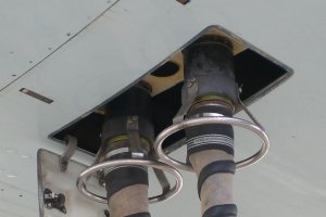 Three external connectors (two on the left duct and one on the right duct) are provided to connect a ground source of high pressure air directly to the bleed air duct.
Two connections are recommended for two pack operation or engine start. During severe cold weather ground air may have to be supplied through all three connections for engine start.
Check valves prevent reverse flow of bleed air from the bleed air duct to the connectors.
Bleed Air Duct System
Duct Pressure Indicator
The Duct Pressure Indicator displays the pressure in the left and right bleed air ducts. These pressures should be approximately equal.
Isolation Valve
The Isolation Valve separates the bleed air ducts into isolated segments. The Isolation Valve is normally closed except for engine start or single bleed source operation.
With the Isolation Valve closed, each engine supplies air to its corresponding:
- Air Conditioning Pack
- Wing Anti-Ice ducting
- a common manifold for the Hydraulic System Reservoirs
The isolation VALVE light illuminates and the EICAS advisory message BLEED ISLN VAL displays when the isolation valve position disagrees with the commanded position.
Bleed air leak detection along the pneumatic ducts is provided by leak detection loops. The loops are continuous elements that activate when a bleed air leak is detected.
![]() The DUCT LEAK light illuminates and the EICAS caution message L/R BLD DUCT LEAK displays when a high temperature bleed air leak is detected. The leak must be isolated and the bleed source turned off to prevent structural damage. When the temperature along the duct has cooled sufficiently, the message disappears and the light extinguishes.
The DUCT LEAK light illuminates and the EICAS caution message L/R BLD DUCT LEAK displays when a high temperature bleed air leak is detected. The leak must be isolated and the bleed source turned off to prevent structural damage. When the temperature along the duct has cooled sufficiently, the message disappears and the light extinguishes.
Engine Anti-Ice
- See: Ice and Rain Protection - Anti-Ice and Rain