Anti-Ice and Rain - Engines
Amendment: Link to Boeing Technical Bulletin regarding high altitude ice crystals. Both TAI indication and EPR adjustment are signalled by switch position - not valve position.
- Limitations - Engine Ignition
- Supplementary Procedures - Anti-Ice and Rain
- Supplementary Procedures - De-Icing
- Boeing - Convective Weather Containing Ice Crystals Associated with Engine Power Loss and Damage
Engine Anti-Ice System

The Engine anti-ice system uses engine bleed air to provide engine cowl inlet ice protection. Engine anti-ice can be operated in flight or on the ground. The left and right engines have identical, independent anti-ice systems. This allows the remaining system to operate if one engine fails.
The cowl anti-ice valves are electrically controlled and pressure actuated. An open cowl anti-ice valve permits the cowl leading edge to be anti-iced by engine bleed air.
- See also Pneumatics section.
Engine Anti-Ice System Operation
On the ground or in flight, pushing the ENGINE ANTI-ICE switches ON allows engine bleed air to anti-ice the engine cowl inlets. The engine Thermal Anti-Ice (TAI) annunciation appears above the EICAS N1 indication when an engine anti-ice valve is selected open.
The VALVE light illuminates and the EICAS advisory message L/R ENG ANTI-ICE displays when the engine anti-ice valve disagrees with the switch position.
When the Engine Anti-ice switches are selected ON, the following also occurs:
- The Engine Idle setting is increased.
- The Maximum EPR limit is reduced. Note: The adjustment is based on the position of the Switch, not the position of the valve.
- For flame-out prevention from ice ingestion, Engine Ignition is automatically activated when the Engine Anti-Ice Switch is turned on, provided the Engine Start Selector is in AUTO.
Thermal Anti-Ice Duct Burst (Pop-Out) Indicator
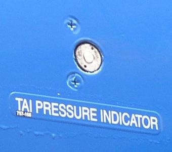 Some engines have a Thermal Anti-Ice Duct Burst (Pop Out) Indicator installed on the left side of the fan cowling.
Spinner Anti-Ice
 Spinner anti-ice is provided by a flexible rubber tip that sheds ice as it oscillates.