Air Systems - Air Conditioning 
Amendment: QRH again recommends FL350 in the event of PACK OFF.
- Limitations - Air Conditioning
Introduction
The air-conditioning system supplies conditioned bleed air and recirculated cabin air at a controlled temperature throughout the airplane, by processing bleed air from the airplane Pneumatic System (Engines or APU) or from a ground source.
The system supplies conditioned air to the flight deck shoulder heaters [and] ventilation for the cabin:
- Lavatories
- Galleys
- Individual passenger seat gaspers
Pack control, zone temperature control, cabin air recirculation, fault detection and overheat protection are all automatic
The airplane is divided into three temperature zones: the flight deck and two cabin zones.
Air Conditioning Packs
Two identical air conditioning packs cool bleed air from the airplane Pneumatic System (Engines or APU) or high pressure air from a ground source. Bleed air is pre-cooled before entering the pack.
Pack Controllers
The packs are controlled by two identical Pack Controllers. Pack output is automatically increased (High Flow) during high pack demand periods (to compensate for a failed pack or recirculation fan) or limited during high bleed air demands (such as with an engine inoperative).
Positioning the selector to AUTO or STBY sends an open signal to the Pack Valve.
Pack Valves
The Pack Valve is a flow control valve and requires air pressure to open. When open, the valve limits air flow to a scheduled rate based on airplane altitude.
Air Conditioning Automatic Mode
With the Pack Selector in the AUTO position, pack output temperature is determined by the Cabin Temperature Controller. Zone temperature is then satisfied by the Zone Temperature Controllers using Trim Air.
Conditioned air from the packs flows into a common manifold where it mixes with air from two recirculating fans. The mixed air is then ducted into the temperature controlled compartments of the airplane.
Pack High Flow
Certain operating conditions require the pack(s) to provide higher than normal air flow for adequate air conditioning and pressurisation. This is accomplished by a pack high air flow system. The system is automatic and armed for operation at all times.
The pack high flow system controls the pack valve to open to a second schedule and provide more airflow for:
- During ground operation whenever the APU or ground source is supplying air for air conditioning (both packs HIGH).
- If one pack is INOP.
- If a recirculation fan is INOP.
The pack high flow system is inhibited when:
- Wing anti-ice is ON and only one engine is supplying bleed air
- an Engine is INOP
- Flaps are not UP
- aft cargo compartment ARMED switch pushed
When a pack is operating in high flow, the displayed EPR limit for the associated engine is automatically reduced.
Air Conditioning Standby Mode
With the Pack Selector in the Standby mode, pack output temperature is determined by the position of the Pack Selector:
- N (Normal) - constant, moderate temperature (approximately 24°C}.
- C (Cool) - full cold (as dictated by ambient conditions).
- W (Warm) - full warm. Outlet temperature is controlled by ram air flowing across the pack heat exchangers and will be dependent upon ambient conditions.
Ground Conditioned Air Operation
When a ground source of conditioned air is available, it may be used to supply conditioned air directly to the cabin air distribution system, eliminating the need for pack operation. Air from the ground source enters the left air conditioning manifold and is routed through the mix manifold to the cabin distribution ducts.
Pack Non-Normal Operation
Pack Control, zone temperature control, cabin air recirculation, fault detection and overheat protection are automatic.
Pack INOP
When an automatic control fault or a pack overheat is detected, the pack automatically shuts down. The pack INOP illuminates and the EICAS advisory message L/R PACK TEMP displays.
• Pack Automatic Control System Fault
If the INOP Light extinguishes immediately upon selecting STBY, the fault is in the Automatic Control System. The pack temperature control valves freeze in the last controlled position. The pack cannot be reset in this case and must be operated in Standby.
• Overheat in Pack Output Air
If the INOP light remains after selecting STBY, the fault is a pack overheat. The Pack will automatically set to maximum cooling.
Pack Reset Switch
After the pack has cooled (5 minutes), an attempt to restore pack operation may be made by pushing the Pack Reset switch.
• Internal Pack Overheat
If the PACK OFF light illuminates together with the INOP light and the EICAS advisory message L/R PACK OFF, a pack trip due to an internal pack overheat is indicated.
The PACK OFF Light illuminates and the EICAS message L/R PACK OFF displays whenever the Pack Valve is Closed. The Pack Valve will Close if:
- The Pack Control Selector is OFF.
- A pack trip has occurred.
- (With associated Engine Bleed Air OFF light illuminated) - Loss of air to the pack.
Packs Off Take-Off
During a Packs Off Take-Off, both engine Bleed Air Valves may close due to low air demand, with associated L/R ENG BLEED OFF advisories.
Air Distribution
Conditioned air from the packs flows into a mix manifold where it mixes with air from two recirculation fans. Recirculation fans maintain overall cabin air circulation while allowing a reduction of cabin air ventilation, permitting the packs to be operated at a reduced flow. The mixed air is then ducted into the cabin.
The flight deck receives 100% fresh conditioned air from the left pack only and is maintained at a slightly higher pressure than the passenger cabin. This prevents smoke from entering the flight deck. When the left pack is inoperative, the flight deck receives air from the mix manifold.
Recirculation Fans
The Left Recirculation fan draws air through the Forward Electrical/Electronic Equipment Cooling System, main instrument panels, overhead panels and Weather Radar and returns it into the mix manifold.
The Right Recirculation fan draws air from the passenger cabin into the forward cargo compartment sidewalls. From there it is blown by the recirculation fan into the mix manifold.
The Right Recirculation fan can be turned OFF for several minutes to provide a more rapid exchange of air. The Left Recirculation Fan should not be turned OFF as this causes the Overboard Exhaust Valve to latch Open. Maintenance action is required after landing to reset this valve.
 The Recirculation Fan INOP Light illuminates and the EICAS advisory message L/R RECIR FAN displays whenever a Recirculation Fan fails or is not operating. A slight increase in fuel consumption occurs for each fan that is OFF.
Compartment Temperature Control
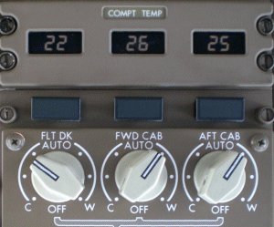 The airplane is divided into three (-200) or four (-300) temperature control compartments:
- Flight Deck
- Forward Cabin
- Mid Cabin (-300)
- Aft Cabin
The Pack Controllers regulate the pack output air temperature to satisfy the temperature requirement of the compartment requiring the coolest air.
Trim Air
Hot Trim Air from the bleed air system (obtained downstream of the Pack Valves) is added through Trim Air Valves to control the temperature in each of the other compartments.
Each of the three (-200) or four (-300) temperature control compartments has an associated Temperature Controller which modulates Trim Air to satisfy the increased temperature requirements.
- AUTO - Automatic temperature control in the range 18° to 30° C.
- OFF - Closes the Compartment Trim Air Valve and the INOP light illuminates.
Compartment Temperature INOP
![]() A compartment INOP light illuminates and the EICAS advisory message FLT DECK TEMP, FWD CABIN TEMP, MID CABIN TEMP, AFT CABIN TEMP displays to indicate:
A compartment INOP light illuminates and the EICAS advisory message FLT DECK TEMP, FWD CABIN TEMP, MID CABIN TEMP, AFT CABIN TEMP displays to indicate:
- A fault in the Zone Temperature Controller
- the Trim Air switch is OFF
- the Compartment Temperature Control is OFF
Temperature Control with Loss of Trim Air System
![]() During operation with the Trim Air System OFF, the Cabin Temperature Controller attempts to maintain all compartments at an average temperature (24°C). The Trim Air OFF Light illuminates and the EICAS advisory message TRIM AIR displays when the Trim Air switch is OFF.
During operation with the Trim Air System OFF, the Cabin Temperature Controller attempts to maintain all compartments at an average temperature (24°C). The Trim Air OFF Light illuminates and the EICAS advisory message TRIM AIR displays when the Trim Air switch is OFF.
Shoulder and Foot Heaters
Flight crew shoulder heat is provided by Electric elements in the side window air diffusers. The HIGH setting is available in flight only, but the LOW setting is available both in flight and on the ground. The foot heaters have electric heating elements only, with no airflow. Foot heaters are available in flight only.
Zonal Dryer
AMM
The Zonal Drying system keeps the humidity in the crown area at a level where it will reduce the condensation on the fuselage skin inner surface and stop water accumulation in insulation blankets. By creating differential vapour pressure in the intermediate space on the aircraft the crown area and subsequently the side walls will dry out.
The system consists of one Zonal Dryer installed behind the AFT Cargo compartment, close to the Potable Water tank. The air is led to and from the Zonal Dryer via three light weight ducting systems.