Warning Systems - EICAS
Amendment: Link to document listing NO-GO Status Messages.
Introduction
The warning systems consist of four separate systems:
- Engine Indication and Crew Alerting System (EICAS).
- Warning System.
- Ground Proximity Warning System (GPWS).
- Traffic Alert and Collision Avoidance System (TCAS).
These systems provide all airplane crew alerting. Alert is defined as a visual, tactile and/or aural alert requiring crew awareness and possible crew action.
- For information on EICAS-related engine indications, see Engines - EICAS
Engine Indication and Crew Alerting System
EICAS consolidates engine and subsystem indications and provides a centrally located crew alerting message display. EICAS also displays some system status and maintenance information. EICAS provides:
- System alerts.
- Maintenance information.
- Status messages
- As installed - communication alerts.
All alert and status messages are listed in the Dispatch Deviation Guide or airline equivalent and provide a cross reference to the MEL (Minimum Equipment List) for possible dispatch relief.
System Alert Messages
System alert messages are normally associated with system failures or faults that may require performance of a specific non-normal procedure, or affect the way the flight crew operates the airplane. There are four categories of crew alerts:
Non-normal airplane system conditions not affecting the normal operation of the airplane are not alert conditions. These are annunciated using status or maintenance messages.
System alert messages not directly caused by system failures or faults include such situations as:
- Overspeed Warning
- FMC messages
- TCAS warnings
- As Installed - Windshear Warning
Non-normal operational conditions do not include:
- Communication indications
- Interphone calls
- SELCAL
- As installed - Printer messages (SB changes displays printer messages)
System Alert Level Definitions
Time Critical Warnings
Time critical warnings alert the crew of a non-normal operational condition requiring immediate crew awareness and corrective action to maintain safe flight. Time critical warnings are usually associated with primary flight path control. Master warning lights, voice alerts, and ADI indications or stick shakers announce time critical warning conditions.
Warnings
Warnings alert the crew to a non-normal operational or system condition requiring immediate crew awareness and corrective action.
Cautions
Cautions alert the crew to a non-normal operational or system condition requiring immediate crew awareness. Corrective action may be required.
Advisories
Advisories alert the crew to a non-normal operational or system condition requiring routine crew awareness. Corrective action may be required.
Communication Alerts
As installed
Communication alerts are triggered by the communication management system. These alerts direct the crew to the appropriate message display. There are three levels of communication alert:
- Low - identifies an incoming communication requiring timely awareness and response.
- Medium - identify an incoming communication requiring immediate awareness and a prompt response. It is accompanied by an aural chime.
- High - reserved for future use.
- See also: Communication Crew Alerting System
Status Messages
Status messages identify system faults affecting airplane dispatch and are not considered crew alerts. The messages are displayed on the EICAS STATUS page.
Alert Message Displays
Alert messages are displayed in both prioritised and chronological order. The priority in descending order is:
- Warning (red)
- Caution (amber)
- Advisory (amber, indented)
- As installed - Medium level communication (white, preceded by a dot)
- As installed - Low-level communication (white, indented, preceded by a dot)
Warnings, cautions, and advisories are displayed from the top down in the EICAS display message area.
The most recent message is displayed at the top of its respective level.
New display messages appear on the page being viewed. For example, if page three is selected and a new caution occurs, the caution message appears on page three below any warning messages. If the Recall Switch is subsequently pushed, the new caution message appears as the top caution message on page one.
 If the number of messages exceeds eleven, the area below the alert field displays a page cue, indicating more than one page of messages is available for display. Paging is accomplished by pushing the CANCEL/RECALL switch on the display select panel.
Warning alerts can only be cleared by correcting the condition causing the warning. All caution and advisory alerts can be cleared. When the last page is displayed, pushing the CANCEL/RECALL switch clears all displayed caution and advisory alerts. Cleared caution and advisory alerts whose conditions still exist can be recalled by pushing the CANCEL/RECALL switch again. This also recalls the first page for review.
Communication Alerts
As installed
Communication alert messages are displayed at the bottom of the message area. An overflow of system alert messages displaces communication alerts. The bottom line of the EICAS message field (line 11) is reserved for a communication alert (medium or low) if one is active. The communication alert line cannot be displaced by a system alert even if more than 10 lines are active.
As installed
Communication alerts are removed when a pilot selects the appropriate switch on the Pilot's call panel.
Master Warning/Caution Reset Switches and Lights
Two master warning/caution reset switches each contain a master WARNING light and master CAUTION light.
The red master WARNING lights illuminate when any warning alert or time critical warning occurs (except a stall warning). The lights remain illuminated as long as the warning alert exists or until either master warning/caution reset switch is pushed. Pushing either switch:
- Extinguishes both master WARNING lights.
- Resets the lights for future warning alerts.
Pushing either master warning/caution reset switch also silences the warning siren and fire bell except for the following warnings:
- Landing configuration (for example, when the flap lever is in a landing flap setting and landing gear are not down).
- Autopilot disconnect.
- Takeoff configuration.
- Overspeed warning.
The amber master CAUTION lights illuminate when any caution alert occurs. The lights remain on as long as the caution alert exists or until either master warning/caution reset switch is pushed. Pushing either switch:
- Extinguishes both master CAUTION lights.
- Resets the lights for future caution alerts.
Flight Deck Panel Annunciator Lights
Flight deck panel annunciator lights are used in conjunction with EICAS messages to:
- Help locate and identify affected systems and controls.
- Reduce the potential for error.
The annunciator lights provide system feedback in response to flight crew action. The lights also assist in fault detection and system pre-flight configuration when the engines are shut down and to supplement EICAS information.
Aural Alerts
Aural alerts are provided to ensure crew attention, recognition, and response. Aural alerts include synthetic voices and tones. Aural voice alerts are the most direct and rapid method of communicating a specific alert condition to the crew. Aural tones are used to alert the crew and to discriminate between the different alert types and levels.
Aural alerts annunciate time critical warning, warning and caution alerts. There are no aural alerts associated with advisory level alerts.
As installed
Aural alerts also annunciate medium level communication alerts. There are no aural alerts associated with low-level communication alerts.
The aural alerts are:
Beeper - used for all system alert caution level messages. The beeper consists of a tone that sounds four times in a second. The beeper automatically silences after one series of four beeps.

Bell - used for fire warnings. The bell sounds repeatedly until crew action is initiated.
Voice - synthetic voices annunciate time critical warning alert conditions. Synthetic voices also annunciate certain normal but time critical operational information, such as approach phase altitude callouts.
As Installed - Siren - used to annunciate cabin altitude, autopilot disconnect, configuration and overspeed warning alerts. The siren consists of alternating high and low tones.
As Installed - Siren - used to annunciate cabin altitude and configuration warning alerts. The siren consists of alternating high and low tones.
As Installed - Clacker - used to annunciate overspeed warning.
As Installed - Wailer - used to annunciate autopilot disconnect warning.
As Installed - Chime - a high-low tone chime used for medium level communication alerts. The chime sounds once for each communication alert.
All continuous aural alerts are silenced automatically when the respective alert condition no longer exists.
Status Page
When the Status Switch is pushed, the status display appears on the lower CRT. System indicators appear in the top left corner of the display. These indications are described in the systems chapters.
White, status messages appear on the right side of the status display. These messages indicate equipment faults that require awareness at dispatch and that are not otherwise shown in the cockpit.
Status messages are arranged by order of occurrence. The most recent status message appears at the top of the list.
If there is an additional page of status messages, pushing the Status Switch displays the next page. When the last page of messages is displayed, pushing the switch again removes the status display from the lower CRT and blanks the screen.
New status messages appear at the top of the page being viewed. If the status display is deselected and subsequently reselected the message list is reordered, with the newest status message now appearing at the top of the first page.
A Status Cue appears in the upper left corner of the lower CRT if a new status message occurs and the status display is not currently selected. The cue disappears when the status page is displayed. Status messages do not need to be checked in flight, however, they can be useful in anticipating possible ground maintenance actions.
Flight control positions for the rudder, ailerons and elevators appear in the bottom left corner of the status display. Brake temperature and tyre pressure indications appear on the lower right side of the status display.
- See also: Flight Controls - General
- See also: Landing Gear - Brake Temperature
Maintenance Control Display Panel
The maintenance portion of EICAS is used to monitor, record and retrieve maintenance information associated with systems and engine performance.
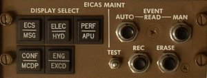 The EICAS MAINT control panel provides a means of monitoring additional real time parameters for maintenance information and can also be used to retrieve recorded displays of systems information, engine performance data and engine exceedances stored in the EICAS computer memory due to an AUTO or MAN Event. This information is used by maintenance for trend analysis and troubleshooting airplane systems. Retrieval of this information is inhibited during all flight operations.
The DISPLAY SELECT switches are used to display ECS/MSG (Environmental Control Systems/Maintenance Messages), ELEC/HYD (Electrical/Hydraulic), PERF/APU (Performance/Auxiliary Power Unit), CONF/MCDP (Configuration/Maintenance Control Display Panel) and ENG EXCD (Engine Exceedances) pages.
The maintenance displays appear on the lower CRT when the Display Select Switches are pushed. Pushing the Display Select Switch again or the Engine Switch cancels the maintenance mode and returns the EICAS displays to the engine indicating mode. The maintenance mode is also cancelled by pushing the Status Switch, returning the Lower CRT to the status mode of operation.

EICAS Event Record
The flight crew can manually capture and record any suspect condition into EICAS memory using the EICAS EVENT RECORD switch.
Systems which provide recorded information when the switch is activated include:
- Air Systems
- Anti-ice and Rain
- APU
- Electrical System
- Electronic Engine Control
- Fire Protection System
- Flight Controls / Flaps And Slats
- Fuel System (quantity and management)
- Hydraulic System
- Landing Gear and Brakes
- Performance
Only the last manual event recorded will be retained for future retrieval. The event record function also has an automatic feature. When an EICAS event occurs, conditions are automatically written to EICAS memory.
AUTO EVENTS are instantaneously recorded when system or engine limits are exceeded and are restricted to one event per page for systems and two events for engines. However, when a red band exceedence occurs after an amber band exceedence has been recorded. the first auto event is automatically replaced by the higher priority second auto event. The auto event must be cleared before a second auto event of the same Level can be recorded for that system.
MANUAL EVENTS may be recorded by pressing the pilot's EVENT RECORD switch. A subsequent manual event can be recorded for that system by pressing the switch again. Only the last manual event recorded will be retained for future retrieval.
The AUTO and MAN EVENT READ switches select data from the Auto or Manual Event computer memory for display when a DISPLAY SELECT switch is pushed.
Clearing Messages
EICAS Failure Indications
If a fault is detected in one of the cathode ray tubes (CRTs), the faulty display is blanked. Engine indications and crew alerting messages appear on the operable display. An EICAS DISPLAY advisory message displays when one CRT fails.
When a CRT fails, status can only be displayed on the ground.
To ensure that all engine indications can be displayed with a CRT failure, an EICAS compacted display mode is available.
- See: Engines - EICAS for a description of the compacted display mode.
If the EICAS control panel fails an EICAS CONT PNL advisory message displays and the EICAS full up engine mode automatically displays. The cancel and recall switches will not operate when the EICAS control panel fails, however, brightness and computer select controls remain operative.
- See: Engines - EICAS for a description of the full engine mode.
 If both EICAS computers or CRTs fail, a Standby Engine Indicator (SEI) is automatically activated. The SEI, system lights and indicators are used to monitor the engines and system operation when a total EICAS failure occurs.
EICAS Test
A test of EICAS is initiated with the EICAS Test Switch. The test can only be displayed on the ground with the parking brake set. When the test switch is pushed, a beeper and siren sound, the Master and warning Caution Lights illuminate, test patterns appear on both CRTs and the Standby Engine Indicator comes on. A configuration warning also occurs. A TEST IN PROGRESS message appears during the test and disappears when the test is complete. A TEST OK message then appears if the test is passed. A TEST FAIL massage appears if faults detected. Pushing the test switch once more cancels the test and returns the displays to the engine indicating mode.
Push the ECS/MSG switch on the EICAS MAINT panel on the right side panel to see the ECS/MSG page.
Push the AUTO-EVENT READ switch. (Make sure that AUTO EVENT shows at the bottom of the lower display.)
Push and hold the ERASE switch for 3 seconds. Note: The ERASE switch performs two functions: it erases all messages that are in view and it moves the display forward to show the next page of messages.
Continue to push the ERASE switch until PAGE does not show or until PAGE 1 shows again.
Note: All maintenance messages that still show after the erase procedure identify continued failures.