Automatic Flight - AFDS 
Amendment: Boeing Flight Operations In-Service Acrivieties Report 93-03 (Autothrottle System Operation in the Flight Level Change Mode) included.
- Limitations - Automatic Flight
- Limitations - Autoland
- Boeing - Flight Director Pitch Command Differences on Takeoff
- Boeing - AFDS Mode Control Panel Faults
- Boeing - Autothrottle System Operation in the Flight Level Change Mode
- Boeing Fleet Newsletter - Low-Level Altitude Capture
Introduction
The Autoflight System (AFS) consists of the:
- Autopilot Flight Director System (AFDS)
The Mode Control Panel (MCP) and Flight Management Computer (FMC) control the AFDS and, with the Thrust Mode Select Panel (TMSP), the Autothrottle system to perform climb, cruise and descent.
Autopilot Flight Director System
The AFDS consists of three Flight Control Computers (FCCs) and the MCP.
The MCP provides control of the autopilot, flight director, Altitude Alert, and Autothrottle systems. The MCP selects and activates AFDS modes, and establishes altitudes, speeds, and climb/descent profiles.
Flight Control Computers
The three FCCs, left, centre, and right, control separate hydraulically powered autopilot control servos to operate flight controls. The autopilot controls ailerons and elevators. Rudder commands are added only during a multiple autopilot approach, landing and rollout. Nose wheel steering is also added during rollout from an automatic landing. During an ILS approach with all three autopilots engaged, separate electrical sources power the three FCCs.
Autopilot engagement requires at least two operable FCCs. Commands from the two FCCs are compared to prevent one FCC from commanding an autopilot hardover. The left AC bus normally powers the left and centre FCCs except during Autoland operations after Bus Isolation occurs. When the electrical busses are isolated for an automatic Landing, the centre FCC receives power from the Hot Battery Bus and Standby Inverter. If Left AC Bus power is lost inflight, the left and centre FCCs will be unpowered. With only the right FCC powered, no autopilots can be engaged; however, the right flight director will operate.
The FCCs also provide inputs for AFDS operating mode displays and Flight Director commands on the EADI.
MCP Switches
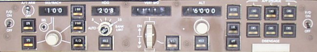
Mode Control Panel
[click on an area for more information]
MCP switches select automatic flight control and flight director modes. A light in the lower half of the switch illuminates to indicate the mode is armed or active. Respective roll and pitch flight mode annunciations on the FMA will also display to indicate mode engagement. Autothrottle modes are discussed later in this section.
Most modes activate with a single push. These modes include:
- Flight level change (FLCH).
- Heading hold (HDG HOLD).
- Heading select (HDG SEL).
- Vertical speed (V/S).
- Altitude hold (ALT HOLD).
Other modes arm or activate with a single push. These modes are:
- ILS Approach (APP).
- As installed - Back course localiser (B/CRS).
- As installed - Control wheel steering (CWS).
All modes deactivate by disengaging the Autopilot and turning both Flight Directors off. After localiser and glideslope capture, the localiser and glideslope modes can only be deactivated by disengaging the autopilot and turning both flight directors off or by selecting GA mode. When armed, VNAV, LNAV, LOC, B/CRS and APP modes can be disarmed by pushing the mode switch a second time.
Desired target values can be selected on the MCP for:
- Airspeed.
- Mach.
- Heading.
- Vertical speed.
- Altitude.
All parameters except vertical speed can be preselected before autopilot and/or flight director engagement.
Autopilot Engagement
Autopilot engagement requires at least two FCCs and pushing one of the MCP autopilot engage switches.
Autopilot Disengagement
Normal autopilot disengagement is through either control wheel autopilot disengage switch.
As installed
The autopilots can also be disengaged by the MCP autopilot disengage bar.
The A/P DISC light illuminates and the EICAS warning message AUTOPILOT DISC displays when the autopilot has been manually or automatically disconnected.
AFDS Failures
During single autopilot operation, failures affecting the active mode annunciate on the FMA. If the failure affects only the active mode:
- The autopilot remains engaged in an attitude-stabilising mode.
- An amber line is drawn through the mode annunciation.
- The AUTO PILOT light illuminates.
- The EICAS caution message AUTOPILOT displays.
If unwanted operation is noticed or when an autopilot failure is annunciated the autopilot should be disconnected and the airplane flown manually.
Failures affecting all autopilot modes result in an autopilot disengagement accompanied by an aural warning. Depending on the system failure, it may be possible to re-engage an autopilot by pushing the autopilot engage switch.
Flight Director Display
Flight director steering indications normally display any time the related F/D switch is ON.
The steering indications are also displayed when the related flight director switch is OFF and a go-around switch is pushed, if airspeed is greater than 80 knots and the flaps are not retracted. In this case, the flight director display can be removed by cycling the respective flight director switch on and then off.
A flight director failure in either pitch or roll causes the respective steering bars to disappear. If both axes become unusable, both command bars disappear.
AFDS Flight Mode Annunciations
Flight mode annunciations are displayed on the EADI. Mode annunciations from left to right are:

| Autothrottle | Pitch | Roll | AFDS status |
Active modes display at the top of the flight mode annunciation boxes in large green letters. Armed modes (except for TO on the ground and GA in flight) display in smaller white letters at the bottom of the fight mode annunciator boxes. When a mode changes, the new active mode is highlighted with a green rectangle around it for several seconds.
Notes:
F/S appears only when Autothrottle is disengaged, AFDS is not operating in a speed mode (FLCH or GA) and the present airspeed is approaching either SPD LIM, ALPHA or FLAP LIM.
An amber horizontal line is drawn through the appropriate pitch or roll mode word when a flight mode fault is detected.
AFDS/Autothrottle mode changes are emphasised for 10 seconds by a box (green) drawn around the word.
Autothrottle Modes
FMA Autothrottle annunciations are:
EPR - Autothrottle controlling to the selected EPR reference thrust.
SPD - Autothrottle controlling thrust to maintain speed selected in IAS/MACH or, if VNAV engaged, the speed as programmed by the FMC.
IDLE - Autothrottle is reducing or has reduced thrust to idle. It may engage in a VNAV descent. It will, after FLARE is engaged.
THR HOLD - Thrust levers remain in existing position or where manually placed. The Autothrottle servos are de-energised.
FLCH - Autothrottle controlling to a maximum of the selected mode reference thrust during climb, and to a minimum thrust during descent.
GA - Autothrottle controlling to a maximum reference thrust to maintain a climb rate of at least 2000 fpm. If both flight directors and the autopilot are off, Autothrottle controls to go-around reference thrust subject to flap and VMO limit speeds.
Roll Modes
Roll annunciations are:
LNAVArm LNAV by pushing the LNAV switch. The light illuminates and LNAV annunciates on the FMA roll mode annunciator in white characters below the current roll mode.
HDG
ATT
LOC
B/CRS (As Installed)
TO
GA
ROLLOUT
|
Pitch Modes
Pitch annunciations are:
TOOn the ground, TO annunciates by selecting either F/D switch ON when both flight directors are OFF. The flight director pitch bar indicates an initial pitch of approximately eight degrees up. After takeoff, the AFDS commands a pitch attitude to maintain:
Note: AFDS uses the speed set in the IAS/MACH window prior to takeoff for V2. GAAfter the reference thrust limit changes from takeoff to climb, GA arms whenever:
When a go-around is initiated the commanded speed is the MCP IAS/MACH window or current airspeed, whichever is higher. If the airspeed increases and remains above the initial target airspeed for five seconds, target airspeed resets to current airspeed to a maximum of the IAS/MACH window speed plus 25 knots. If airspeed at initiation of go-around is greater than IAS/MACH window plus 25 knots, that speed is maintained. GA displays as the reference thrust limit on the primary EICAS engine display. VNAVArm VNAV by pushing the VNAV switch. The light illuminates and VNAV annunciates on the FMA pitch mode annunciator in white characters below the current pitch mode. VNAV provides pitch commands to maintain the FMC computed airspeed/path:
V/SPushing the V/S switch opens the vertical speed window and displays the current vertical speed. It also opens the IAS/MACH window (if blanked). Pitch commands maintain the rate of climb or descent selected in the V/S window. SPDPushing the SPD switch opens the IAS/MACH window (if blanked). Pitch commands maintain IAS/MACH window airspeed or Mach. ALT CAPA transition manoeuvre entered automatically from a V/S, FLCH, or VNAV climb or descent to selected MCP altitude. Engages but does not annunciate during VNAV transition. ALT HOLDAltitude Hold mode is activated by:
G/SAutopilot flight director system follows the ILS glideslope. FLARE
|