Flight Instruments - Air Data 
Amendment: Explanation of TAT Probe Heat operation.
- QRH - AIRSPEED UNRELIABLE
The air data system consists of:
- the pitot-static system
- one Total Air Temperature (TAT) probe
- two Angle Of Attack (AOA) Sensors
- two Air Data Computers (ADCs)
- and the Electric Flight Instruments.
The system provides pitot and/or static pressure information to various flight instruments and airplane systems.
The two Air Data Computers use air data information to provide input signals to certain flight instruments:
and other using systems:
Standby Airspeed and Altimeter Indicators are also provided.
The left instruments use the left ADC and the right instruments use the right ADC. The opposite ADC is available as an alternate air data source. Warning flags indicate instrument failure or unreliable data. When a malfunction occurs in instruments with failure monitors, warning flags appear.
Non-Normal Indications
The EICAS caution messages ALT DISAGREE or IAS DISAGREE display when there is a significant difference (200 ft/5 kts) between the left and right air data information. These messages are inhibited at low altitude or when both pilots have the same air data source selected.
Boeing An erroneous overspeed warning can result from a malfunctioning ADC or pitot/static system even though the flight crew has selected an alternate ADC source. The ADC overspeed warning source is not controlled by the position of the ADC switch.
Pitot-Static System Schematic
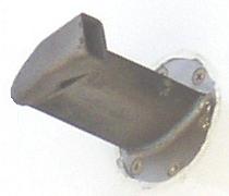
Total Air Temperature
Total Air Temperature (TAT) appears on EICAS above the EPR display and is supplied by a Thrust Management Computer or Air Data Computer. The TAT indication is comprised of outside air temperature (OAT) plus ram rise. TAT indication on the ground will approximate OAT.
 AMM
The total air temperature (TAT) probe is electrically heated to prevent erroneous readings due to ice conditions, and is automatically controlled by air/ground relays. On the ground the TAT probe is not heated. The condition of the TAT light depends on the right and left ENG OUT relays. If both engines are off, the left and right engine speed cards de-energise the ENG OUT relays, and the TAT light comes on. If one engine is on, the engine speed card energises the corresponding ENG OUT relay. Therefore, with at least one engine operating on the ground, both the TAT probe heater and TAT light are off.
AMM
The total air temperature (TAT) probe is electrically heated to prevent erroneous readings due to ice conditions, and is automatically controlled by air/ground relays. On the ground the TAT probe is not heated. The condition of the TAT light depends on the right and left ENG OUT relays. If both engines are off, the left and right engine speed cards de-energise the ENG OUT relays, and the TAT light comes on. If one engine is on, the engine speed card energises the corresponding ENG OUT relay. Therefore, with at least one engine operating on the ground, both the TAT probe heater and TAT light are off.
Bleed air provided by the engine bleed air distribution manifold creates a negative pressure which draws outside air across the sensing elements at such a rate that the anti-ice heaters have a negligible effect. This feature permits accurate TAT readings to be displayed while the airplane is on the ground or in-flight at low airspeeds.
True Airspeed/Static Air Temperature
True Airspeed (TAS) and Static Air Temperature (SAT) are displayed on the PROGRESS page.
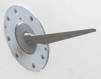
Angle of Attack Sensors
 AMM
The Angle of Attack (AOA) sensors measures the direction of airflow relative to the fuselage. The sensor vane aligns itself with the prevailing airstream, rotating a central shaft. A viscous damper in the AOA vane stabilises vane movements and reduces the effects of turbulence. The sensor has a solid-state vane heater which provides continuous de-icing/anti-icing. The AOA sensor also has a case heater which prevents condensation and reduces changes in damper fluid viscosity.
AMM
The Angle of Attack (AOA) sensors measures the direction of airflow relative to the fuselage. The sensor vane aligns itself with the prevailing airstream, rotating a central shaft. A viscous damper in the AOA vane stabilises vane movements and reduces the effects of turbulence. The sensor has a solid-state vane heater which provides continuous de-icing/anti-icing. The AOA sensor also has a case heater which prevents condensation and reduces changes in damper fluid viscosity.Air Data System (757-300)
The air data system consists of the pitot-static system, seven Air Data Modules (ADMs), two temperature probes (TATs), two angle of attack probes, three Air Data Inertial Reference Units (ADIRUs) and the electric flight instruments. The ADMs convert analogue data to digital and send it to the ADIRUs. The ADIRUs combine the functions of an air data computer with an inertial reference system. The inertial reference function of the ADIRUs is described in the Flight Management Navigation section. Under normal operating conditions, only the left or right ADIRU can be selected as an alternate source using the air data switch since the air data portion of the centre ADIRU is not normally connected. The IRS portion of the centre ADIRU can be selected as an alternate source using the IRS switch. The system provides pitot and/or static pressure information to various flight instruments and airplane systems. Standby airspeed and altimeter indicators are also provided.
Non-Normal Indications
The ADIRUs use air data information to provide input signals to certain flight instruments (Mach/Airspeed Indicator, Primary Altimeter) and other using systems (AFDS, FMC, etc.). The left instruments use the left ADIRU and the right instruments use the right ADIRU. The opposite ADIRU is available as an alternate air data source
Warning flags indicate instrument failure or unreliable data. When a malfunction occurs in instruments with failure monitors, warning flags appear. The EICAS caution messages ALT DISAGREE or IAS DISAGREE display when there is a significant difference between the left and right air data information. These messages are inhibited at low altitude or when both pilots have the same air data source selected. The EICAS advisory message, SINGLE AIR DATA displays when both pilots have selected the same air data source. displays when air data faults are detected within the respective ADIRUs, or air data modules that interface with that ADIRU.
Boeing On certain aircraft, the Captains altimeter settings are followed irrespective of autopilot selection. A summary follows:
Air-Data Source - Basic FMC
In VNAV mode, the autopilot obtains altitude commands from the FMC. 200K FMC normally use the Left Air Data Computer (ADC) for altitude information. Therefore, in VNAV mode, the Left ADC supplies the altitude data and will match the Captains Altimeter irrespective of which autopilot is in operation.
Other autopilot modes, for example FLCH, obtain altitude commands from the Flight Control Computer (FCC). Each FCC normally uses Left ADC for left and centre Autopilot and Right ADC for right Autopilot.
Air-Data Source - PIP/ Pegasus FMC
In VNAV mode, the autopilot obtains altitude commands from the FMC. However, to make autopilot ADC selection more consistent, Boeing modified the air data source logic within the FMC so that left FMC uses left ADC and right FMC uses right ADC. Therefore, VNAV mode on these aircraft will not differ from other FCC controlled modes. Captains altimeter settings are followed for left and centre Autopilot operation, F/O altimeter settings are followed for right Autopilot.
G-FCLC Right IRS U/S
In this event the F/O source select switch is set to ALTN, the centre IRS uses Right ADC data instead of the normal Left ADC. Therefore the Right ADC feeds the centre A/P, altitude set in the MCP will match the F/Os altimeter. In this event the Transponder should be set to ATC 2.