Flight Instruments - Primary Conventional
- QRH - AIRSPEED UNRELIABLE
- Limitations - RVSM
- Boeing - Vmo/Mmo Limitations Review
Introduction
The conventional instruments provide information in addition to the EFIS displays to aid pilots in controlling the airplane throughout its flight regime. This section includes a discussion of the Primary Instruments, Standby Instruments and the Pitot Static System.
Mach/Airspeed Indicator
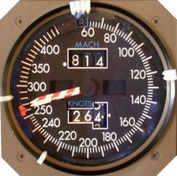 Two Electric Mach/Airspeed Indicators display airspeed, mach, and Vmo from the selected Air Data Computer. The Vmo pointer indicates the maximum operating airspeed in knots or the equivalent to the maximum operating Mach number.
The command airspeed bug on each indicator can be automatically positioned from the FMC, or manually from the MCP IAS/MACH selector.
Primary Altimeter
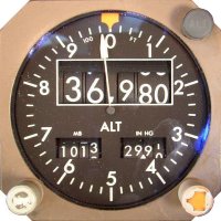 Two electric altimeters indicate current altitude in feet from the selected Air Data Computer. An altimeter altitude light is provided.
Radio Distance Magnetic Indicator
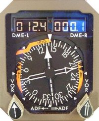 Two Radio Distance Magnetic Indicator (RDMI) are installed. Each displays magnetic heading or true heading, VOR or ADF bearing, and (VOR/ILS/DME, VORTAC) distance. The RDMI receives primary heading signals from the opposite side IRS and alternate heading signals from the C-IRS. The RDMI is inoperative until the associated IRS has completed alignment and entered the navigation mode.
With the heading reference switch in NORM, magnetic heading is displayed if the airplane is outside Polar Regions (73°N to 60°S). In Polar Regions, a heading flag shows. When the switch is in TRUE, true heading is displayed regardless of latitude.
When the RDMI is referenced to true north, positioning an ADF/VOR selector to VOR causes the associated pointer failure flag to appear. When operating on standby power and referenced to true north, no VOR radio navigation capability exists.
Vertical Speed Indicator
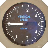 Two electrically-driven vertical speed indicators (VSI) are installed. The captain's VSI is connected to the left IRS and ADC, and the first officer's VSI is connected to the right IRS and ADC.
The centre IRS provides backup vertical speed data for either crewmember when ALTN is selected with the respective IRS switch. The opposite ADC provides backup vertical speed data for either crewmember when ALTN is selected with the respective AIR DATA switch.
The VSI is inoperative until the associated IRS has completed alignment and entered the navigation mode.
As installed
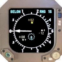
On some airplanes TCAS Information is displayed on the VSI. Traffic symbols appear in the centre of the display relative to airplane position. Resolution Advisories are shown by red and green arcs displayed on the vertical speed scale. The red arc indicates vertical speeds to avoid, and the green arc (if displayed) indicates vertical speeds to fly.