Flight Instruments -
Electronic Flight Instrument System (EFIS) 
Introduction
The Electronic Flight Instrument System (EFIS) consists of:
- three (L, C & R) Symbol Generators (SGs)
- two Control Panels (CPs)
- two Attitude Director Indicators (ADIs)
- two Horizontal Situation Indicators (HSIs)
- and ambient light sensing units.
The EFIS uses information provided by a variety of aircraft systems to generate the appropriate visual presentations on the ADI and HSI. Data relating primarily to navigation is provided by aircraft systems such as:
Data relating primarily to automatic flight is provided by:
- the Flight Control Computers (FCCs),
- the Autothrottle (A/T)
- and the FMC
757-200
Data which is used to display current aircraft state information is provided by the two Air Data Computers (ADCs) and the three Inertial Reference Systems (IRSs).
757-300
Data which is used to display current aircraft state information is provided by the three Air Data/Inertial Reference Units (ADIRUs). The ADIRUs combine the functions of an Air Data Computer with an Inertial Reference System.
Automatic adjustment of the display intensity for each display unit is provided by the Ambient Light Sensing Units. Flight crew control of the EFIS displays is accomplished by positioning the various controls on the respective EFIS control panels to the desired settings.
EFIS Symbol Generators
Three symbol generators form the heart of the EFIS. The SGs receive inputs from various aircraft systems, then generate the proper visual displays for the related EADI and EHSI. Each pilot's ADI and HSI displays are provided from the SG selected with their respective EFI switch. The left SG normally provides the captain's displays, and the right SG normally provides the first officer's displays. The centre SG is available as an alternate source for either or both pilots. When both pilots select ALTN with their EFI switches, the Left system instrument sources supply data to the C-SG. However, the C-SG always uses the centre ILS and centre Radio Altimeter.
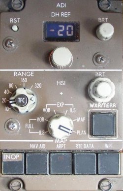
EFIS Control Panels
The EFIS control panels control display options, modes, ranges and brightness for the respective EADI and EHSI.
Each ADI and HSI Control Panel is connected to the symbol generator with the EFI switch. Each IRS switch permits pilot selection of the alternate data source for heading, attitude and vertical speed.
EFI/IRS Interface Diagram
The following diagram shows the normal EFI/IRS interface.
EFI switching determines the Centre Symbol Generator (C-SG) input and output. Normally, left system instrument sources supply the centre SG. When both pilots select ALTN with their EFI switches, the left system instrument sources supply data to the centre SG. However, the Centre SG always uses the centre ILS and centre Radio Altimeter.
Each EFIS control panel is connected to the symbol generator with the EFI switch. Each IRS switch permits pilot selection of the alternate data source for heading, attitude and vertical speed.
Lights Test Switch
When a Lights TEST switch on the overhead panel is pushed, the ADI and HSI will display a maintenance test pattern. A message stating TEST OK or TEST FAIL, and the name of the failed component, appears at the end of the test. This test is inhibited in flight.
EFIS Failures Flags and Annunciation
In addition to the normal EFIS displays, various failure annunciations, flags, or indications may be displayed on the ADI or HSI.
When each of the three SG's are powered, the displays are provided on the appropriate ADI and HSI. When not powered the displays are blank.
A blank screen results when a power failure or over-temperature condition exists. Partial loss of colour capability may cause an odd colour presentation. When Information is not reliable or radio signals are not received, the display is removed. Numeric indications are replaced with dashes. If airplane equipment fails, a failure flag is displayed. (Note: Some symbol generator installations cannot display the LOC and/or GS flags on the EADI.)
The location of the different failure flags and annunciations is depicted in the ADI and HSI Failure Flags and Annunciations figures included in the EFIS Controls and Indicators, section 10 of this chapter.
Not all EFIS displays will be replaced by a failure flag or annunciation if the signal from the sending unit has failed. In theses instances, failure is indicated by removal of the data or the affected portions of the display.
During preflight, heading/track data is unavailable until the associated IRS has completed alignment and entered the navigation mode. Heading flags do not appear in this case.
If an FMC FAIL message is observed on a CDU, a MAP flag will appear on the associated HSI when viewing the MAP mode. Selecting the opposite FMC with the NAV selector will restore the map display. With the opposite FMC selected, the other pilot has control of the HSI range. A MAP RANGE DISAGREE message is displayed on the HSI when the range selections differ.
If both FMCs fail, selecting CDU on the NAV selector will allow the CDU to provide limited map data to the HSI.
Various fault messages can also be displayed on the HSIs. For example, a WXR/MAP RANGE DISAGREE message is displayed when the ranges for the FMC and weather radar disagree with the range selected on the HSI control panel.
 An EXCESS DATA message is displayed if the quantity of information to the display exceeds the HSI's capability to provide a normal display. If in the MAP mode, deselecting the map switches may correct the condition and remove the message.
Light Sensing and Brightness Control
Ambient light sensors automatically adjust the brightness of the EFIS displays. Once the desired brightness is set using the EFIS brightness controls, little or no adjustment is needed throughout a wide range of ambient light conditions both outside and inside the flight deck.