Flight Instruments -
Electronic Attitude Director Indicator (EADI)
- QRH - AIRSPEED UNRELIABLE
- Boeing - 757-300 PLI and Stick Shaker Activation
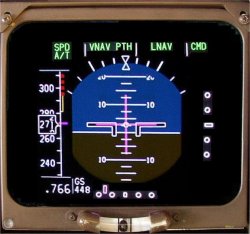
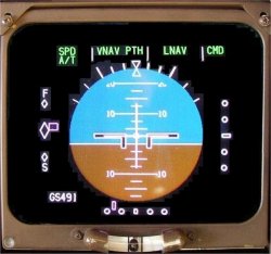 The ADI presents conventional displays for attitude (pitch and roll), flight director commands, localiser deviation and glide slope deviation. In addition, the ADI displays information relating to autoflight system mode annunciations, airplane speed, Pitch Limit, Radio Altitude and decision height.
As installed
TCAS RA pitch commands are also displayed.
The captain's attitude information is provided by the left IRS and the first officer's information is provided by the right IRS. The centre IRS provides that data as an alternate source.
Attitude Display
Airplane attitude data is provided by the IRSs. The IRSs pitch and roll attitude information is valid throughout 360 degrees of rotation in each axis.
Mode Annunciations
Mode annunciations for the A/T and the AFDS are displayed at the top of the ADI displays.
- For a detailed description of the various autoflight mode annunciations and their meanings refer to the Automatic Flight section.
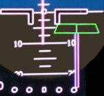
Flight Director Commands
Flight director guidance commands from the selected FCC are displayed via the flight director symbol on the ADI. A flight director failure in either axis causes the command bar to disappear and the FD flag appears. If both axes become unreliable, both command bars disappear and the FD flag appears. [Single-Cue Flight Directors]
IRS alignment must be completed before flight director commands can be displayed.
Glide Slope and Localiser Deviation Displays
Conventional ILS information is provided from the ILS receiver selected with each pilot's EFI switch. All three ILS receivers are commonly tuned on the ILS panel.
The glideslope pointer is not displayed when glideslope unusable or when aircraft track and the front course selected on the ILS panel differ by more than 90°.
ILS Deviation Warning
ILS localiser and glide slope deviations are monitored when below 500 feet Radio Altitude with the mode control panel APP switch selected ON. An alert is displayed if a significant deviation from localiser (more than one fifth dot for one sec) or glide slope (more than one dot for one second) occurs: the respective deviation scale changes colour from white to amber and the associated pointer flashes. If a localiser alert, the stem of the rising runway symbol also flashes. The alert stops when deviation returns to within normal limits. The glide slope alert is inhibited when below 100 feet Radio Altitude.
Rising Runway Symbol
 The rising runway symbol is an integral part of the LOC deviation display and is positioned at the top of the LOC deviation pointer. The rising runway symbol is displayed in addition to the Radio Altitude display and gives an additional cue to the flight crew of the aircraft's close proximity to the ground as the airplane descends below 200 feet Radio Altitude. Full scale, vertical movement of the rising runway represents the last 200 feet of Radio Altitude. Zero feet Radio Altitude is indicated as the top of the runway symbol rises to the base of the airplane symbol.
The rising runway symbol displays when the localiser pointer is displayed and Radio Altitude is below 2500 ft.
Attitude Comparator
The EICAS caution message ATT DISAGREE displays, the Master Caution Lights illuminate and the caution aural sounds when a difference of more than 3 degrees between the captain's and first officer's pitch or roll displays is detected. An amber PITCH or ROLL alerting annunciation is displayed on both ADIs for the parameter that is out of tolerance. Attitude comparison monitoring is inhibited when both pilots are using the centre symbol generator by selecting ALTN on the EFI switches.
Instrument Comparator Unit
An Instrument Comparator Unit (ICU) monitors the ADIs for cross cockpit agreement. The EICAS caution message ATT DISAGREE displays when pitch or roll parameters are out of tolerance. ICU comparison monitoring is inhibited when both pilots are using the centre symbol generator by selecting ALTN on the EFI switches.
As installed
An Instrument Comparator Unit (ICU) monitors the HSIs for cross cockpit agreement. The EICAS advisory messages LOC FAIL (localiser), or G/S FAIL (glideslope) display when a localiser or glideslope flag is displayed on either of the ADIs or HSIs. ICU comparison is inhibited when both pilots are using the centre symbol generator by selecting ALTN on the EFI switches.
During pre-flight, attitude data is unavailable until the associated IRS has completed alignment and entered the navigation mode. The ATT (attitude) flag does not appear in this case.
Height Alert
As installed
The height alert ALT is triggered when the airplane descends below 2,500 feet AGL. The alert is turned off when the airplane continues to descend below 500 feet AGL, or climbs above 2,500 feet AGL, or after pressing the decision height reset switch on the EFIS control panel.
Radio Altitude and Decision Height
AMM The Radio Altimeter (RA) system supplies vertical position data for use by the pilots for runway approach, landing, and takeoff. The RA system provides accurate measurement of absolute altitude (height above terrain) from 2500 ft to touchdown. Three complete systems are installed. Each system consists of a receiver/transmitter (R/T), and one transmit and one receive antenna.
When radio altitude is less than 2,500 feet AGL, a digital display is depicted on the ADI. At all other times, the digital radio altitude display is blanked.
When a positive decision height has been selected on the related EFIS control panel, the letters DH and the decision height are displayed just above the digital radio altitude display of the associated ADI. Selecting a negative DH blanks the DH display but does not affect the RA display.
When descending through the selected decision height, a decision height alert occurs. The display changes from white to amber, increases in size and DH flashes momentarily.
The decision height alert is reset if any one of the following occurs:
- The DH reset switch on the EFIS control panel is pressed.
- The Radio Altitude increases to above Decision Height +75 feet.
- The Radio Altitude is equal to zero feet (i.e. during touchdown).
As Installed
 On some airplanes, a radio altitude ring and scale encircle the digital radio attitude readout when below 1000 feet RA. As the airplane descends, segments of the ring erase indicating radio altitude. The ring is calibrated in increments of 100 feet. On airplanes with the radio altitude ring, the decision height is displayed as a magenta marker on the altitude ring when below 1000 feet. When descending through the selected DH, the radio attitude ring, the ring, scale, marker, and digital RA display change to amber and flash for several seconds.
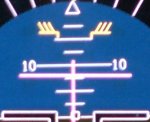
Pitch Limit Symbol
 As Installed
The position of the pitch limit symbol is a function of the stall warning computer. This symbol is displayed any time the flaps are extended. It is programmed so that stick shaker activation will coincide with a pitch attitude equal to the pitch limit symbol indication.
Ground Speed Display
A digital presentation of the current ground speed is displayed. The ground speed data is received from the FMC or the IRS, with the FMC being the primary source.
Airspeed Display
Speed Tape Fitted
Airspeed is displayed on a tape on the ADI. The current Mach number is digitally displayed below the airspeed tape when the current Mach number is greater than 0.40.
The selected airspeed, takeoff and landing reference speeds, and flap manoeuvring speeds are shown on the airspeed tape. Maximum and minimum airspeeds are also displayed on the airspeed tape.
Airspeed Display
The Fast/Slow pointer is positioned by the Thrust Management Computer.
|
||||||||