Flight Management Navigation - Radio Navigation System
Amendment: Link to Honeywell Weather Radar Manual.
- Boeing - VOR/ILS Failure Detection
- Boeing - False Localiser Captures
Radio Navigation Systems comprise:
- Automatic Direction Finding (ADF)
- Distance Measuring Equipment (DME)
- VOR
- Marker Beacon
- Instrument Landing System (ILS)
- Pegasus - Multi-Mode Receiver
- Pegasus - Global Positioning System (GPS)
- Transponder
- Weather Radar
Automatic Direction Finding (ADF)
A dual ADF system is installed with a single control panel.
As installed
ADF bearings are displayed on the HSI.
ADF bearings can be selected for display on the RDMIs
- BFO Switch (As Installed) - Activates tone generator (beat frequency oscillator) required for receiving audio from un-modulated stations.
- Mode Selector (As Installed)
- Tone Switch (As Installed) - Activates tone generator (beat frequency oscillator) required for receiving audio from un-modulated stations. The centre position deactivates the tone generator.
Distance Measuring Equipment (DME)
Two DME systems are installed and each can be automatically tuned by the FMC or manually tuned by the VOR or ILS control panel.
DME Tuning
When an ILS or VOR mode is displayed on the HSI, the related ILS or VOR control panel tunes the DME.
When the HSI selector is in a MAP or PLAN position automatic FMC tuning or manual VOR panel tuning can be selected with the MAN/AUTO switch on the VOR control panel.
The DME can also be remotely tuned on the CDU by entering a VOR frequency or identifier on the NAV RADIO page on PEGASUS FMCs or the PROGRESS page on other FMCs.
The FMC uses two DMEs for position updates. If only one DME is available the FMC can use that DME and the associated VOR for a VOR/DME update.
The NAVAID INHIBIT function on the REF NAV DATA page prevents the FMC from tuning navaids which have been entered by the flight crew.
DME Displays
DME distance is displayed on the RDMI. When the DME is tuned by the ILS receiver the distance display is preceded by an L. DME distance is also displayed on the HSI when operating in the VOR or ILS mode.
The identifiers and associated VOR or ILS frequencies of the DME stations used by the FMC for position updates are displayed on the PROGRESS page on non-PEGASUS FMCs and on the NAV RADIO page on PEGASUS FMCs.
DME Audio
When the related HSI Mode Selector is NOT in the ILS position, DME audio is heard by using the VOR Receiver Control on an audio selector panel. In the ILS position, DME audio is heard by using the ILS Receiver Control.
VOR
There are two VOR receivers and two control panels installed. The VORs are normally tuned by the FMC but, can be tuned manually.
VOR Tuning
- Boeing - VOR/ILS Failure Detection
In normal operation the FMC tunes both VORs and the associated DMEs for radio position updates. The HSI must be in a MAP or PLAN mode to allow FMC tuning of the VOR. Specific VOR/DME navaids can be inhibited on the REF NAV DATA page to prevent the FMC from using those navaids for position updating.
The crew can tune the VORs manually using the control panels, or remotely using the CDU. If the HSI selector is not in a MAP or PLAN mode, the associated VOR must be manually tuned using the control panel. If the HSI is in a MAP or PLAN mode, the AUTO/MAN Switch on the control panel must be selected to MAN to manually tune the VOR.
The tuned VOR frequencies and identifiers are displayed on the NAV RADIO page on airplanes with the PEGASUS FMCs installed and on the PROGRESS page on other airplanes. The VORs can also be remotely tuned from these pages if the VOR control panel is in AUTO.
VOR Displays
Left and right VOR bearings can be displayed on the RDMIs. When the VOR display is selected on the HSI, the selected course, frequency and course deviation are displayed. If the HSI is in a MAP mode, symbols indicate the position of tuned VORs and the selected course of manually tuned VORs are displayed.
The tuned frequencies and selected courses are displayed on the VOR control panels on the glareshield.
If the HSI is in a MAP mode, symbols indicate the position of tuned VORs and the selected course of manually tuned VORs are displayed.
The identifier and frequency of the navaid tuned on the left and right VOR are displayed on the PROGRESS page.
Marker Beacon
Each pilot has a set of marker beacon lights that show outer, middle and inner/airways beacon passage. Both sets are operated by the marker beacon receiver that is part of the left VOR receiver.
Multi-Mode Receiver
PEGASUS
Three Multi-Mode Receivers (MMRs) are installed. Each MMR includes an ILS and GPS receiver. The GPS receiver in the centre MMR is not used.
Instrument Landing System (ILS)
- Boeing - VOR/ILS Failure Detection
- Boeing - False Localiser Captures
Three ILS receivers are installed. They are controlled by a single control panel on the aft aisle stand. Frequency changes are inhibited after localiser or glideslope capture if three autopilots are armed for approach. The selected runway front course is locked to prevent changes when the localiser is captured.
- Tuned frequency displayed in frequency window.
- Received data is displayed on the EADI.
- If selected, ILS data is displayed on the related EHSI and the associated DME is tuned to the ILS frequency.
- VOR frequencies cannot be tuned.
- Frequency change is inhibited when all three autopilots are armed and either localiser or glideslope is captured.
- Dashes are displayed when tuned to the standby position, and ILS symbology is removed from the EADI.
ILS Displays
Localiser and glideslope deviation are shown on the ADIs and can be selected on the Standby Attitude Indicator and HSI. The ILS display on the HSI includes the selected front course and frequency in addition to the localiser and glideslope deviation.
Front or back course deviation is determined from airplane heading.
Global Positioning System (GPS)
PEGASUS
Left and right GPS receivers are independent and supply very accurate position data to the FMC. The GPS receivers are contained in the left and right Multi-Mode Receivers (MMRs). All GPS tuning is automatic.
GPS Displays
Position Reference, page 3 of 4 (POS REF 3/4) displays the left and right GPS position.
GPS Data
The FMC uses GPS data to refine the FMC position if the GPS is enabled and the GPS data is valid. If GPS data is not available or is unreliable the FMC will use the navigation radio position or IRS position data.
The GPS NAV prompt on POS REF 3/4 can be used to inhibit GPS navigation data. The EICAS message GPS alerts the crew when data from both GPS systems are unavailable or when both systems have failed.
GPS position updates are allowed for all United States National Airspace approach operations. Outside of this region, GPS position updates are allowed during approaches only if the FMC database and approach charts are referenced to the WGS-84 reference datum. GPS updates should be inhibited for all other approach operations unless other appropriate procedures are used.
Transponder
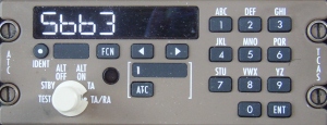 There are two ATC transponders installed. They are controlled by single control panel and provide normal transponder functions and altitude reporting. The control panel is used to set the ATC code, operating mode, and to select which transponder is active.
- unique airframe identifier assigned by CAA.
- Altitude reporting in 25ft increments.
- Flight Status (airborne/on the ground).
- Indicated Airspeed/Mach No
- Selected Altitude/Flight Level (from MCP)
- Magnetic Heading
- Ground Speed
- Vertical Rate (baro-inertial rate of climb/descent)
- Track and Turn Report (Roll Angle, Track Angle Rate, True Track Angle
- ACAS Active Resolution Advisory (RA) - controller 'sees' what you see
- backwards compatibility with SSR Mode 3/A
The transponder is also capable of providing traffic alert and collision avoidance system (TCAS) indications. Select TA ONLY or TA/RA to enable traffic displays.
- Refer to: Warning systems, TCAS for a description of TCAS.
Failure of a transponder is indicated by the illumination of the amber ATC FAIL light on the control panel and the ATC FAULT advisory message on EICAS.
Weather Radar
- Boeing - New Generation Weather Radar
- Boeing - Weather Radar Tilt Setting
- Honeywell - Weather Radar Manual
 2.1Mb
2.1Mb
 The weather radar system consists of a single receiver-transmitter, an antenna, and a control panel. If the aircraft has a dual installation, the control panel selects which R/T unit is used.
As installed
There is also a dedicated weather radar indicator installed on the forward aisle stand. Radar returns are displayed on the indicator and can also be displayed on the HSI by selecting the EFIS control panel WXR switch on.
The EFIS control panel weather radar (WXR) switch controls power to the transmitter/receiver and selects the weather radar display on the respective HSI. The radar display range is set by the HSI range selected on the EFIS control panel. The receiver-transmitter is activated when either WXR switch is on.
The IRS provides antenna stabilisation and is controlled by the captains IRS select switch. In NORMAL, the left IRS provides stabilisation, while in ALTN the centre IRS provides stabilisation.
- AUTO - Provides automatic gain control calibrated for optimum return.
- Rotate - Provides manual control of radar gain. Gain is increased as control is rotated towards MAX.
- WX - Displays weather returns at selected gain level.
- TURB - Displays weather returns plus turbulence. Turbulence is only shown on display ranges of 40 nm or less.
Turbulence can be sensed by the weather radar only when there is sufficient precipitation. Clear air turbulence cannot be sensed by radar.
As installed
The Predictive Windshear Alerting System uses the weather radar to sense windshear. To provide windshear alerting the weather radar transmitter is activated on the ground when takeoff power is set and in flight when the airplane is below 2300 feet Radio Altitude. Windshear detection is active even if the radar switch is in the OFF position. Radar returns are not displayed unless the WXR switch is ON.
Radio Altimeter
There are three Radio Altimeters (RAs) that supply vertical position data for use by the pilots for runway approach, landing, and takeoff. The Radio Altimeters provides accurate measurement of absolute altitude (height above terrain) from 2500 ft. to touchdown. Altitude data is displayed on the EADIs.