Airplane General - Lavatories
The following notes are from the Maintenance Manual
Vacuum Waste System
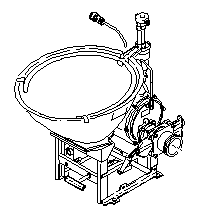
 The toilet assembly consists of an electronic flush control, a rinse valve and a flush valve.
Turning the flush handle actuates the flush control unit to start the flush cycle. The flush control unit controls the operation of the rinse valve and flush valve and the timing of the flush cycle. Starting the flush cycle opens the solenoid-operated rinse valve for 2 seconds, directing potable water through a rinse ring to provide rinse water to clean the bowl during the flush cycle. The flush control unit then opens the motor-operated flush valve for 4 seconds, allowing vacuum pressure in the waste tanks to remove debris from the toilet bowl.
A manual flush shutoff valve is mounted on the downstream side of the flush valve. The manual flush shut off valve is operated by a handle on the front of the toilet to shut off the vacuum waste line if the flush valve fails.
A manual shutoff valve in the rinse water supply line behind the toilet shroud turns off the water supply to the toilet, whilst an antisiphon valve prevents backflow of rinse water from the flush circuit to the potable water system.
Toilet waste Tanks
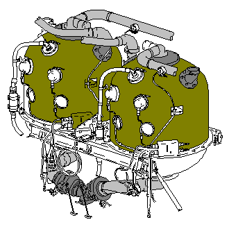
 The two independent toilet waste systems remove and store toilet waste in two 63 USG waste tanks. Two systems are used to ensure continuing toilet waste removal if one system fails. Waste is removed from the toilet bowls by creating a vacuum in the waste tanks. This vacuum draws the waste through waste lines into the waste tank. Vacuum blowers, in the waste tank overboard vent lines, create the vacuum needed for toilet flush at low altitudes and on the ground. Differential pressure between cabin pressure and outside ambient pressure supplies the vacuum during high altitude flight.
Each tank has a rinse nozzle near the top next to its point level sensors. The rinse nozzle washes the inside wall of the tank and the the surface of the point level sensors during servicing. Each waste tank has two inlet waste line connections near the top of the tank. At the top of each tank is a water separator. The water separator removes moisture from the waste tank air before the air is vented. A vacuum blower is in the overboard vent line coming from each tank. The vented air from the water separator goes through the vacuum blower when the airplane is not at flight altitude, or through the vacuum blower check valve (bypassing the vacuum blower) when the airplane is at flight altitude.
Toilet Service Panel
-
Closed Waste System
Two waste service panels, one for each pair of forward and mid toilets, are located on the underside of the fuselage. Each service panel has a single waste drain valve assembly fed by both tanks and two rinse fittings and two waste valve handles.
-
Vacuum Waste System
The waste service panel, for the waste disposal system, is on the bottom of the fuselage just right of the centreline near the aft end of the airplane. The service panel has a single waste drain valve assembly fed by both tanks and two rinse fittings and two waste valve handles. When the service panel door is opened, two proximity switches stop power to the vacuum blowers. This will stop the toilet system operation during waste tank servicing.