Electrics - Hydraulic Driven Generator 
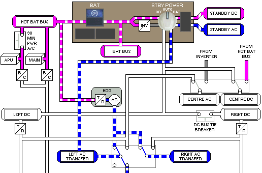
The hydraulic driven generator (HDG) activates automatically when both the left and right main AC buses are unpowered. The hydraulic driven generator is powered by the Centre Hydraulic System.
The hydraulic driven generator provides AC power to the:
- Left and Right AC Transfer Buses.
- Standby AC Bus (via the Left AC Transfer Bus).
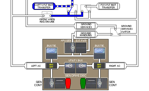
- Captain's Flight Instrument Transfer Bus.
The hydraulic driven generator provides DC power to the:
The amount of DC power produced by the hydraulic driven generator is less than the DC power produced by fully charged main and APU batteries. When the hydraulic driven generator first begins to operate, the MAIN BAT DISCH and APU BAT DISCH lights may illuminate until the battery power decreases to the power level produced by the hydraulic driven generator.