Fuel System - Jettison 
Note: The above schematic is an extremely simplified depiction of the Aircraft Fuel System.
 The fuel jettison system allows jettison from the center fuel tank. Fuel is jettisoned through nozzles inboard of each outboard aileron. The common fuel manifold allows jettison pumps in the center tank to pump fuel overboard.
Two dual pump units provide a high capacity jettison rate of approximately 1200 kg per min.
 Fuel jettison begins when:
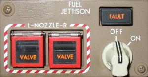
- the FUEL JETTISON selector is selected ON
- the jettison transfer valves open
- the FUEL JETTISON NOZZLE switches are selected ON
- the nozzle valves open, and
- the jettison pumps operate
The FMC discontinues fuel value calculations and the totalizer value is used during fuel jettison operation. After fuel jettison is complete, the calculated value will reset using the same value as the totalizer value.
The fuel disagree message is not displayed during fuel jettison operation.
As installed
On some airplanes, only one pump in each dual pump unit of the high capacity system is activated, or an interim Fuel Jettison System is installed with only two jettison pumps. The resulting low capacity jettison rate is approximately half that of the high capacity system. Flaps 25 or 30 should not be selected when using a low capacity jettison system.