Fuel System - Description 
- Limitations - Engine Fuel System
- General Information - Approved Fuel Specifications
Note: The above schematic is an extremely simplified depiction of the Aircraft Fuel System.
Introduction
The fuel system supplies fuel to the engines and the APU. The fuel is contained in a centre tank, and left and right main tanks. Surge tanks are provided in each wingtip. Fuel from the surge tanks is drained to the centre tank.
- See also: Engines - Fuel System
- See also: Engines - APU
Fuel Quantity
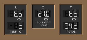
Fuel quantity data, measured by probes in each tank, is fed to the fuel quantity processor where it is corrected for density then displayed on a Fuel Quantity Indicator for each tank. Total fuel quantity, from a separate calculation, is shown on the Total Fuel Quantity Indicator and is also provided to the FMC.
![]() When total usable fuel in either the left or right main tank drops below approximately 1000 kg, the FUEL CONFIG light illuminates and the LOW FUEL caution message is displayed.
When total usable fuel in either the left or right main tank drops below approximately 1000 kg, the FUEL CONFIG light illuminates and the LOW FUEL caution message is displayed.
Fuel Temperature
Temperature of the fuel in the left main tank is displayed on the Fuel Temperature Indicator.
Fuel Pumps
Each fuel tank contains two AC-powered fuel pumps. A single pump can supply sufficient fuel to operate one engine under all conditions.
Centre Tank Override Pumps
The two centre tank fuel pumps have approximately twice the output pressure of the left and right main tank fuel pumps. When all six pumps are operating, the centre tank pumps override the left and right main tank pumps so that centre tank fuel is used before left and right main tank fuel.
To reduce electrical loads, the centre tank pumps are inhibited, both in flight and on the ground, when the associated N2 is Less than 50% RPM. Thus both centre tank pumps are inhibited with the engines shutdown. As an engine is started and N2 RPM increases above 50%, the inhibit is removed for the associated centre tank pump.
AMM (As installed) The right fuel override pump will supply fuel if both AC buses fail and the hydraulic motor generator comes on.
Non-Normal Indications
 If any pump has low output pressure, the appropriate switch PRESS light illuminates and the pump pressure EICAS message (eg L FWD FUEL PUMP) is displayed. If the left or right main tank pump switches are OFF, the low pressure Lights are illuminated and EICAS messages for the pumps are displayed. When the centre pump switches are OFF, the low pressure lights and EICAS messages for the pumps are inhibited.
The EICAS caution messages, L/R FUEL SYS PRESS, displays when all fuel pumps have low output pressure or all fuel pumps on one side have low output pressure and the crossfeed switches are OFF.
The fuel pump low pressure messages are inhibited by the corresponding L/R FUEL SYS PRESS messages.
During normal operation, the EICAS advisory messages CTR L/R FUEL PUMP display to indicate the depletion of centre tank fuel.
With either message displayed, a small amount of centre tank fuel up to 500 kg may be indicated
Centre Tank Scavenge Pump
A scavenge system will operate automatically to transfer any remaining centre tank fuel to the main tanks. Fuel transfer begins when the main tanks are approximately half empty. The transfer rate is approximately 180 kg per hr, but may be as low as 60 kg per hr.
Note: The scavenge pump is a jet pump and requires the left forward main tank fuel pump to be operative.
DC Pump
The Left main tank contains a DC-powered fuel pump. It has no controls or indicators. The DC pump operates automatically to provide fuel to the APU when AC power is not available and the APU selector is ON.
Surge Tanks
AMM A surge tank, outboard of each main fuel tank, collects all overflow fuel passed through the vent channels and supplies fuel tank venting. Two drain check valves permit all overflow fuel to drain back into the main fuel tanks. A vent scoop on the lower wing surface creates a positive pressure during flight. Air flow to the surge tank passes through a vent flame arrestor and through the vent scoop. A pressure relief valve supplies backup venting if the vent flame arrestor becomes plugged. Once opened, the pressure relief valve stays open until it is manually reset.
Fuel Crossfeed
 The fuel manifolds are arranged so that any fuel tank pump can supply either engine. Two cross-feed valves isolate the left fuel manifold from the right. These valves are normally closed providing fuel feed from tank to engine. Both valves are opened any time it becomes necessary to feed an engine from an opposite fuel tank. Only one open crossfeed valve is required for successful cross-feed operation. A VALVE disagreement light illuminates and the EICAS advisory message FWD FUEL X-FEED or AFT FUEL X-FEED displays if a valve position does not agree with its switch position. The L/R FUEL SYS PRESS messages are inhibited with either cross-feed valve open.
Note: The EICAS message FUEL CROSSFEED is displayed when either valve position disagrees with the switch position. A false L/R FUEL SYS PRESS message can occur even though one crossfeed valve is open.
Suction Feed
When main tank fuel pump pressure is low, each engine can draw fuel from its corresponding main tank through a suction feed line that bypasses the pumps. As the airplane climbs, dissolved air is released from the fuel in the tank due to the decrease in air pressure. This air may collect in the suction feed line and restrict fuel flow. At high altitude thrust deterioration or engine flameout may occur as a result of the fuel flow reduction.
Fuel pressure can be provided from a main tank with operating fuel pumps to both engines by opening the fuel crossfeed valve(s). Continued crossfeed use will result in a progressive fuel imbalance.
The dissolved air in the fuel tank will eventually deplete after reaching cruise altitude. The depletion time is dependent upon airplane altitude, fuel temperature and type of fuel. Once dissolved air is depleted, the engine may be capable of suction feed operation at cruise power.
Fuel Configuration Light
![]() The FUEL CONFIG light illuminates and the EICAS advisory message FUEL CONFIG is displayed if:
The FUEL CONFIG light illuminates and the EICAS advisory message FUEL CONFIG is displayed if:
- The fuel quantity in left and right main tanks differs by 900 kg ± 200 kg.
- Centre tank fuel pump switches are OFF with greater than 500 kg in the centre tank.
The FUEL CONFIG light also illuminates when the LOW FUEL EICAS message is displayed.
Boeing The 767 can be flown with one main wing tank full and one tank empty. In the unlikely event of a 767 being in this configuration, up to 30 percent of the available roll control may be required to maintain a wings level attitude during an approach and landing. Thus substantial roll control would remain available for subsequent manoeuvring requirements.
Fuel Imbalance
Fuel balancing is accomplished by opening the crossfeed valves and turning off the fuel pump switches for the left or right main fuel tank that has the lower quantity. Fuel balancing may be done in any phase of flight.
Fuel Tank Capacities
| Left | Centre | Right | Total | |
|---|---|---|---|---|
| 767-300 | 18,267 kg | 36,167 kg | 18,267 kg | 72,700 kg |
APU Fuel Feed
APU fuel is supplied from the Left fuel manifold. APU fuel feed can be provided by any AC fuel pump supplying fuel to the left fuel manifold or by the left main tank DC fuel pump.
On the ground, with the APU selector ON and no AC power available, the DC pump runs automatically. With AC power available, the left forward AC fuel pump operates automatically, regardless of fuel pump switch position, and the DC pumps turns off. In flight, the left forward pump can be turned OFF using the pump switch.
Fuel System FMS CDU Messages
The CDU can display the following messages:
| INSUFFICIENT FUEL | Predicted fuel at destination is less than the FMC reserves. |
| PEGASUS FMC FUEL DISAGREE - PROG 2 |
The fuel totaliser and calculated fuel quantity disagree. |
(SB changes displays Fuel Disagree CDU message.) |
|
| FUEL DISAGREE - PROG 2/2 | The fuel totaliser and calculated fuel quantity disagree. |
| FUEL QTY ERROR - PROG 2/2 | |