Engines - APU
Amendment: Link to APU FIRE drill deleted - no longer a memory/recall drill.
- Limitations - APU
APU Services
- Electrical Power - Max Op Alt
- Start Assured - FL350
- Pneumatic System: 20,000 ft (single pack operation)
- Pneumatic System: 17,000 ft (2 Pack operation)
- In-Flight Crossbleed Engine Start: 14,000 ft
Introduction
The Auxiliary Power Unit (APU) is a self-contained gas turbine located in the airplane tail cone. The APU air inlet door is located between the horizontal and vertical stabilisers on the right side of the airplane.
While the primary purpose of the APU is to supply electrical power and Bleed Air for Air Conditioning on the ground before engine start, the APU can also be started inflight and operated up to the airplane maximum certified altitude.
Electrical power has priority over Bleed Air. Electrical power is available throughout the airplane operating envelope. Bleed air is available to a maximum altitude of approximately 17,000 ft but may be available at higher altitudes depending upon operating conditions and airplane speed.
Refer to the following sections for additional information:
- Air Systems, for a description of APU bleed air operation.
- Electrical, for a description of APU electrical operation.
- Fire Protection, for a description of APU fire protection and the APU Remote Control Panel (located on the right side of the nose gear).
- Fuel, for a description of APU fuel system.
APU Start
APU start requires both the APU battery and aircraft Main battery.
The APU battery supplies power to the APU starter, the air inlet door and the APU control circuitry. The aircraft's Main Battery supplies power for Fire Protection, the APU Fuel Valve and the DC Fuel Pump. It also supplies control circuitry power when the APU battery voltage drops because of heavy starter motor load.
Fuel for the APU is supplied from the left manifold. A dedicated DC fuel pump is energised when the APU Selector is placed in the ON position if no AC power is available. When AC power is available, the left forward AC fuel pump is signalled to operate regardless of its switch position, and the DC fuel pump is signalled off.
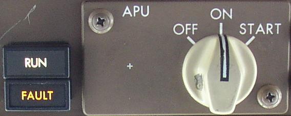
Rotating the APU Selector to START begins the automatic start sequence. The APU fuel valve opens and at the same time the APU inlet door starts to open. A fuel pump also begins to operate.
When the inlet door is fully open, the electric starter engages. After the APU reaches the proper speed, ignition and fuel are provided, and the APU accelerates to its normal operating speed.
APU Start Switch - Contact Bounce
Boeing Operators have reported that the APU Start Switch can fail to initiate an APU start. Intermittent starts are due to variations in the switch contact bounce time when the spring-loaded switch is released from the START to ON position. Contact bounce lasting longer than the interfacing start relay drop-out time (measured as low as 0.75ms) causes the relay to de-energise, removing the START/ON command to the APU Electronic Control Unit, resulting in a failed APU start attempt.
Implementation of the APU Start Switch design change is in progress to install a capacitor across the start relay coil to increase drop-out time to 30ms. In the meantime, crews are advised to manually guide the switch from START to ON to reduce contact bounce.
Starter Duty Cycle
The Starter Duty Cycle is a maximum of 3 consecutive starts or attempts within a 60-minute period.
APU Run
When the APU RUN light illuminates, the APU may be used to supply electrical power and bleed air.
APU Shutdown
To protect the unit from thermal shock, the APU control system incorporates a time-delay feature permitting APU cooling before shutdown. The time-delay is variable from 0 to 120 seconds, but is nominally set at 60 seconds. If the APU is supplying pneumatic power, rotating the APU Selector to OFF begins the shutdown cycle by closing the APU Bleed Air Valve. If the APU Bleed Valve has been closed for a sufficient length of time when the selector is moved to OFF (more than 60 seconds), the APU shuts down without delay.
If the selector is inadvertently moved to OFF, but the RUN light is still illuminated, momentarily moving the selector to START cancels the shutdown signal.
Protection System
On the ground, placing the Battery Switch OFF also results in an APU shutdown. This is not a recommended procedure however, because while the APU will go through a cool-down cycle, APU fire detection may not be available. In flight, Battery Switch position does not affect APU operation.
An amber FAULT light on the APU control panel illuminates whenever a fault is sensed. In addition, an EICAS advisory message APU FAULT is displayed and the APU shuts down immediately. Fault detection circuitry is reset by positioning the APU Selector to OFF.
- one Restart attempt allowed.
The FAULT light also comes on when the APU fuel valve is not in the commanded position. Therefore, during APU Start and shutdown, the light illuminates momentarily. The EICAS advisory message APU FUEL VAL appears if the valve fails to reach the commanded position.
With the APU Selector positioned to OFF, both the APU FAULT Light and the associated APU FAULT EICAS message are inhibited. Only a failure of the APU fuel valve to close causes the FAULT Light and the associated APU FUEL VAL message.