Engines - Controls (GE)
Forward Thrust Levers
Forward Thrust Levers are provided to control engine forward thrust requirements from idle to maximum power.
Reverse Thrust Levers
- See: Thrust Reverse
Thrust Management Computer
- See also: Automatic Flight - Autothrottle
The Thrust Management Computer calculates a reference N1 based on existing pressure altitude and ambient temperature data from the air data system for the following modes:
- TO - takeoff
- D-TO - Assumed Temperature Takeoff
- CLB - Climb
- CLB 1 - Climb One
- CLB 2 - Climb Two
- CRZ - Cruise.
- CON - Continuous.
- GA - Go-Around
 These modes can be selected with the Thrust Mode Select Panel (TMSP). The inner Thrust Reference Set control on the EICAS control panel must be pushed in for the Thrust Reference modes to be displayed on EICAS. The selected Thrust Reference mode is displayed above the N1 indicators. The digital Reference N1 is displayed adjacent to the mode display. When the N1 bug is green, it is positioned on the N1 scale at the same value as the digital reference N1.
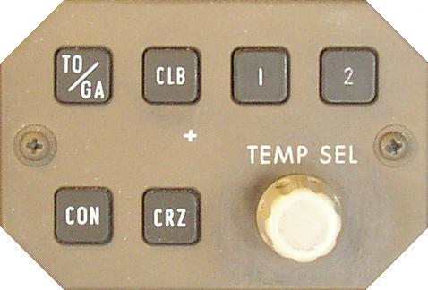
The Thrust Mode Select Switches provide the capability of selecting different thrust modes for each phase of flight:
The TO/GA switch is used to select takeoff thrust on the ground and go-around thrust in-flight.
The 1 and 2 switches are used to select a Reduced Climb Thrust. When reduced takeoff thrust rating one or two is selected, this automatically pre-selects the associated reduced climb one or two. The CLB switch is used to select climb thrust in-flight. If reduced climb thrust one or two was pre-selected, pushing the climb switch in-flight selects CLB 1 or CLB 2.
The CON switch is used to select Maximum Continuous thrust in-flight.
The CRZ switch is used to select Cruise thrust in-flight.
The Assumed Temperature Selector on the TMSP or the CDU TAKEOFF REF page is used to set assumed temperatures when reduced takeoff thrust is desired. The assumed temperature is displayed above the Thrust Reference Mode.
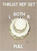 To manually set reference N1 values the Thrust Reference Set Control is pulled out, MAN appears as the thrust mode annunciation and the N1 bug slews to 104%. Manual reference N1 values can then be set by rotating the inner control. The outer control of the Thrust Reference Set Control is used to select the desired N1 indicator(s) for manual N1 display. The autothrottles do not respond to manually set Reference N1 values. When the inner control is pulled out, the autothrottles remain in the active TMC mode. The TMSP remains operable and the autothrottles respond to TMSP mode changes, but selected Thrust Reference Mode displays are inhibited.
When the AFDS VNAV mode is engaged, the N1 bug may be magenta. When the N1 bug is magenta, it is positioned at a nominal target N1 by the FMC, which may not correlate with the digital reference N1. In VNAV, the FMC controls Thrust Mode selection automatically to meet thrust requirements for the active vertical mode of operation. The FMC does not have the capability to select reduced climb thrust values; these values must be selected manually with the 1 or 2 Thrust Reference Mode Select switches.
The Thrust Reference mode, Reference N1 and Target N1 Bug indication are not displayed when the reversers are fully deployed.
Assumed Temperature Takeoff
The Thrust Management Computer calculates the reference N1 for assumed temperature reduced thrust takeoff. The assumed temperature can be entered manually on the CDU TAKEOFF REF page (PEGASUS) or selected with the assumed temperature selector on the TMSP. The assumed temperature is displayed above the thrust reference mode.
When the Assumed Temperature Selector on the TMSP is initially rotated clockwise, a reference temperature is displayed on EICAS. This temperature also appears on the FMC CDU TAKEOFF REF page as THRUST (PEGASUS). Further clockwise rotation of the selector increases the assumed temperature by 1 degree centigrade per click. The reduced thrust annunciation of D-TO appears when the assumed temperature selected is above ambient. If the ambient temperature is greater than the initially displayed reference temperature, D-TO and reduced thrust occur when the assumed temperature selected exceeds ambient.
Counter clockwise rotation of the selector reduces the assumed temperature by one degree centigrade per click.
Assumed temperature takeoff thrust is limited to a 25% reduction of maximum takeoff thrust or selected climb thrust, whichever is the greater thrust value. When the limit is reached, further clockwise rotation of the selector or changing the value entered in the CDU TAKEOFF REF page (PEGASUS) does not change the displayed assumed temperature or reference thrust value.
Reduced Climb Thrust
Two levels of reduced climb thrust are available with the 1 and 2 mode switches on the Thrust Mode Select Panel. Below 10,000 ft, Climb 1 is approximately 90% of climb thrust and climb 2 is approximately 80% of climb thrust. Climb 1 or 2 can be pre-selected in conjunction with the TO, D-TO, CON and CRZ Thrust Reference modes.
Above 10,000 feet reduced climb thrust gradually changes to reach full climb thrust by 12,000 feet. The 1 or 2 annunciation disappears from the display by 12,500 ft.
Electronic Engine Control
The thrust system comprises a hydro-mechanical engine Fuel Control Unit with an Electronic Engine Control (EEC) unit mounted on each engine. Each engine EEC is powered by dual dedicated generators.
Each EEC has full authority over the operation of the engine. The EEC uses thrust lever inputs to automatically control forward and reverse thrust, idle and overspeed. The EEC has two control modes: normal and alternate. In normal and alternate modes, the EEC uses N1 RPM as the parameter for setting thrust.
EEC Normal Control Mode
In the normal mode, the EEC sets thrust by controlling N1 based on thrust lever position. N1 is commanded by positioning the thrust levers either automatically with the autothrottles, or manually by the flight crew.
The EEC continuously computes the maximum limits for thrust. Maximum rated thrust is available in any phase of flight by moving the thrust levers to the full forward positions. Maximum N1 represents the maximum rated thrust available from the engine.
During rapid throttle lever movements, the difference between the engines actual N1 and the EECs commanded N1 is displayed as the Command Sector on the EICAS N1 display.
These values are displayed by the position of the amber radial on the N1 display. If the EEC fails or is turned off, these values are computed by the TMC and displayed in the same manner. If the TMC fails, the maximum limits are blank.
The EICAS advisory message L/R ENG CONTROL and ENGINE CONTROLS displays when faults are detected in the engine control systems. When a failure is detected the EEC trim motor will hold the current trim level until the unit is turned off. These messages are designed to prevent dispatch with these faults.
EEC Alternate Control Mode
If the required signals are not available to operate in the normal mode, the EEC automatically uses the alternate mode. In the alternate mode, the EEC schedules N1 as a function of Thrust Lever position. The alternate mode provides soft and hard levels of control:
SOFT
When the EEC automatically switches and engine to the alternate mode and the EEC mode switch remains in NORM, the EEC is in the soft alternate mode (the switch position is NORM, the EEC mode is alternate). At a fixed thrust lever position, thrust does not change.HARD
When alternate is manually selected on an EEC mode switch, that engine is switched to the hard alternate mode (the switch position is ALTN, the EEC mode is alternate). Reference and target N1, and maximum and commanded N1 values are displayed on the N1 indication during the hard alternate mode. Thrust may change to set the commanded N1 when ALTN is manually selected.As Thrust may increase, when thrust is greater than idle, the Thrust Lever should be moved aft prior to manually selecting the alternate mode so thrust does not exceed maximum N1.
For the normal, soft alternate and hard alternate modes, actual, command, reference/target, maximum and red line N1 information is displayed.
Automatic reversion or manual selection to the alternate mode is indicated by the EICAS advisory message L/R ENG EEC MODE and illumination of the ALTN light on the associated EEC mode switch. Selecting the alternate mode on both engines eliminates thrust lever stagger at equal thrust settings, or asymmetric when the thrust levers are operated together.
The autothrottles remain engaged whenever the EEC automatically switches to the alternate mode. The alternate mode N1 reference/target values are computed by the FMC
Note: Autothrottles remain engaged in the soft or hard alternate modes.
The alternate mode schedule (N1 schedule) provides equal or greater thrust than the normal mode for the same thrust lever position.
Thrust protection is not provided in the alternate mode and maximum rated thrust is reached at a thrust lever position less than full forward. As a result, thrust overboost can occur at full forward thrust lever positions. The EICAS caution message L/R ENG LIMIT PROT is displayed if the thrust lever position commands an N1 greater than the maximum rated thrust (maximum N1).
N1 and N2 red line protection is still available in the alternate control mode.
Overspeed Protection
The EEC also provides N1 and N2 red line Overspeed protection. If N1 or N2 approaches Overspeed, the EEC commands reduced fuel flow.
The EICAS advisory message L/R ENG RPM LIM is displayed whenever N1 or N2 is at the red line limit.
The EEC does not provide EGT over-temperature protection
If engine limit protection is not available, advancing the thrust levers full forward should be considered only during emergency situations when all other available actions have been taken and terrain contact is imminent.
Idle Selection
There are two engine idle speeds:
Minimum Idle. Minimum idle is a lower thrust than approach idle and is selected for all ground operation and for all phases of flight except approach and landing.
Approach Idle. Approach Idle is selected automatically whenever this higher idle setting is required for proper system operation.
During approach and landing when the Landing Gear is down or the Flaps are set to 25 or 30, the idle speed setting increases from minimum to approach. Approach idle setting is maintained until 5 seconds after touchdown to facilitate a faster acceleration for go-around or reverse thrust operation. After the 5 second delay the approach idle speed reverts back to minimum idle to help minimise the landing roll. In-flight when engine anti-ice is turned on, the idle speed setting also automatically increases to the approach setting to maintain higher idle speeds during icing conditions.
The EEC selects these idle speeds automatically.
The EICAS advisory message L/R ENG LOW IDLE displays to indicate that an engine failed to go to approach idle.
The EICAS advisory message IDLE DISAGREE displays to indicate that the engines are at different idle settings. Either one engine has failed to go to approach idle when required or one engine has failed to return to minimum idle. Inflight, to ensure that approach idle is available if required, the thrust lever on the engine with the lower RPM should be advanced to match the engine with the higher RPM.