Engines - Oil System (GE) 
- Company Limitations - Engine Oil Quantity
- Boeing - Flight Crew Considerations for Engine In-Flight Shutdown
The oil system provides pressurised oil to lubricate and cool the engine main bearings, gears and accessory drives. The oil system also provides automatic fuel heating for fuel system icing protection.
The oil system is pressurised by a primary (engine-driven) Oil Pump (driven by the N2 rotor via the accessory gearbox).
From the pump, the oil flows through the primary Oil Filter where contaminants are removed.
Oil is then delivered to the engine main bearings, gears and accessory drives.
A Scavenge Pump (also driven by the N2 rotor) returns the oil to the reservoir.
The oil is cooled by fuel as it flows through the Fuel/oil Heat Exchanger. Depending on the low pressure fuel temperature, the control valve directs oil to either the low pressure heat exchanger or the high pressure heat exchanger or to both.
Prior to the reservoir, the oil flows through a second, scavenge Oil Filter.
Should an oil filter become saturated with contaminates, oil will automatically bypasses the filter. The EICAS advisory message L/R OIL FILTER displays indicating the oil filter is bypassed.
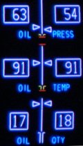
Oil pressure, temperature and quantity are displayed on the secondary engine display.
Oil Pressure is measured upstream of the engine bearings (downstream of the pump) prior to entering the engine, by dual pressure transmitters. The L/R ENG OIL PRESS light illuminates and the L/R ENG OIL PRESS EICAS caution message displays to indicate oil pressure is low. When the oil pressure is at or below the variable limits (normally 18 psi), the EICAS indication changes to amber.
Oil Temperature is measured after leaving the engine, prior to entering the reservoir.
There is no minimum oil quantity limit (no amber or red line limit). There are no operating limitations for the engine oil quantity and there are no flight crew procedures based solely on a response to low oil quantity.