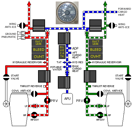
Air Systems - Pneumatics 
Introduction
Bleed air can be supplied by the engines, APU or a ground air source.
Bleed air is used for:
- Wing Anti-Ice and Engine Anti-Ice
- Centre Hydraulic system Air Driven Pump (ADP)
- Hydraulic reservoir pressurisation
Engine Bleed Air Supply
Engine bleed air comes from either the High Pressure (HP) or Low Pressure (LP) engine compressor sections. LP air is used during high power setting operations. HP air is used during descent and other low power setting operations. Control of the HP valve is automatic.
During low engine thrust operation, the HP valve is open allowing high pressure air to power the system. As thrust is increased, the HP valve automatically closes and the LP check valve opens to supply bleed air.
Bleed Air Valves
The engine Bleed Air Valves are armed when the engine bleed air switches are selected ON. The valves are pressure actuated and remain closed until engine bleed air pressure is sufficient to cause forward flow. The valves may close when the APU is starting either engine. The valves may close when Ground Pneumatic Air is connected or during periods of low engine bleed air demand, such as when Air Conditioning Packs are OFF.
The engine bleed air OFF light illuminates and the EICAS advisory message L/R ENG BLEED OFF displays when the engine Bleed Air Valve is closed.
Overpressure
![]() The BLEED light illuminates and the EICAS caution message L/R ENG HPSOV displays when the engine high pressure bleed air valve is open when commanded closed (causing a higher higher than normal pressure). In this occurs, the PRSOV and FWSOV are automatically commanded close and Engine Anti-Ice will not be available.
The BLEED light illuminates and the EICAS caution message L/R ENG HPSOV displays when the engine high pressure bleed air valve is open when commanded closed (causing a higher higher than normal pressure). In this occurs, the PRSOV and FWSOV are automatically commanded close and Engine Anti-Ice will not be available.
The BLEED light illuminates and the EICAS caution message L/R ENG FWSOV displays when the firewall shutoff valve is open when commanded closed.
Overheat
![]() The OVHT light illuminates and the EICAS advisory message L/R ENG BLD OVHT displays when the engine bleed air temperature is excessive, and the the HPSOV and FWSOV automatically close.
The OVHT light illuminates and the EICAS advisory message L/R ENG BLD OVHT displays when the engine bleed air temperature is excessive, and the the HPSOV and FWSOV automatically close.
If Engine Anti-Ice is on or subsequently activated, the FWSOV automatically reopens. High pressure air is available for thrust reverser operation.
When the bleed air temperature cools to a usable level, the bleed air system can be reset by selecting the Bleed Air Switch OFF then ON. This action extinguishes the light and allows the engine bleed valves to operate normally. Only one reset is recommended.
APU Bleed Air Supply
APU bleed air is used primarily during ground operations for Air conditioning Pack operation and Engine Starting. In flight, APU bleed air is available up to approximately 17,000 ft, above which barometric control of APU components automatically reduces APU pneumatic pressure and results in insufficient pressure for cabin pressurisation.
APU Bleed Air Valve
Prior to engine start, pushing the APU Bleed Air Valve switch ON sends an Open signal to the valve. The valve then Opens when the APU reaches normal operating speed.
With the valve open, APU bleed air is supplied to the centre pneumatic duct. If the three isolation valves are open, centre duct air flows into the left and right pneumatic ducts for air conditioning pack operation or engine start.
The APU is protected from engine bleed air pressure by a check valve in the centre pneumatic duct and the APU bleed air valve. System logic between engine operation and the APU bleed air valve closes the engine bleed valve after the first engine is started. After both engines are started, the engine bleed valves are commanded open and the APU bleed air valve will close. The APU bleed air valve cannot be opened unless the centre isolation valve is closed.
The check valve in the APU supply line prevents reverse flow of bleed air from the duct into the APU.
The APU bleed air VALVE light illuminates and the EICAS advisory message APU BLEED VAL displays when the APU bleed valve position disagrees with the commanded position.
Ground Pneumatic Supply
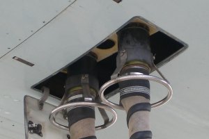 Two external connectors are provided to connect a ground source of high pressure air directly to the bleed air duct.
Check valves prevent reverse flow of bleed air from the bleed air duct to the connectors.
Bleed Air Duct System
A bypass around each isolation valve allows airflow from the engine for forward cargo compartment heat and to supply the centre pneumatic duct.
Centre
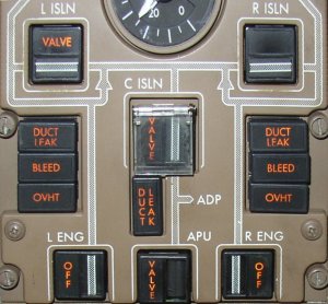
Bleed air flow into or out of the centre pneumatic duct is controlled by the Centre Isolation Switch. The switch is ON for all normal operations.
After engine start, air is bypassed around the left and right isolation valves into the crossover manifold and then into the centre pneumatic duct for distribution to the using systems. Centre duct systems include:
- centre hydraulic system demand air driven pump (ADP)
- aft cargo compartment heat
- bulk cargo compartment heat
- centre hydraulic reservoir
Duct Pressure Indicator
The Duct Pressure Indicator displays the pressure in the left and right bleed air ducts. These pressures should be approximately equal.
Isolation Valves
The Isolation Valves separate the bleed air ducts into isolated segments. The left and right isolation valves are normally closed except for engine start or single bleed source operation. The centre isolation valve normally remains open.
With the left or right Isolation Valve closed, each engine supplies air to its corresponding:
- Air Conditioning Pack
- Thrust Reverser
- Wing Anti-Ice ducting
- Hydraulic System Reservoirs
The isolation VALVE lights illuminate and the EICAS advisory message C, L or R BLD ISLN VAL displays when the bleed isolation valve position disagrees with the commanded position.
Bleed air leak detection along the pneumatic ducts is provided by leak detection loops. The loops are continuous elements that activate when a bleed air leak is detected.
![]() The DUCT LEAK light illuminates and the EICAS caution message L/R BLD DUCT LEAK, BODY DUCT LEAK or STRUT DCT LEAK displays when a high temperature bleed air leak is detected. The leak must be isolated and the bleed source turned off to prevent structural damage. When the temperature along the duct has cooled sufficiently, the message disappears and the light extinguishes.
The DUCT LEAK light illuminates and the EICAS caution message L/R BLD DUCT LEAK, BODY DUCT LEAK or STRUT DCT LEAK displays when a high temperature bleed air leak is detected. The leak must be isolated and the bleed source turned off to prevent structural damage. When the temperature along the duct has cooled sufficiently, the message disappears and the light extinguishes.
If a DUCT LEAK Light and a BODY DUCT LEAK or a L/R BLD DUCT LEAK message remain illuminated and does not go out when the bleed source is turned OFF, a Leak exists between the left and right isolation valves.
Engine Strut Over-Temperature
The DUCT LEAK light illuminates and the EICAS caution message STRUT DCT LEAK displays when a high temperature bleed air leak is detected by dual loop systems in the strut.
If a strut over-temperature occurs, the HPSOV and FWSOV close. If Engine Anti-Ice is used, the FWSOV automatically reopens unless there is a second strut over-temperature. For a strut duct leak, both the message and Light remain illuminated.
Engine Anti-Ice
- See: Ice and Rain Protection - Anti-Ice and Rain