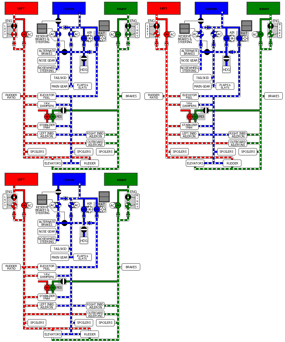
Hydraulics - General 

Introduction
The airplane has three independent hydraulic systems:
The hydraulic systems power the:
Flight control system components are distributed so that any one hydraulic system can provide adequate airplane controllability.
The Left and Right systems are each powered by one engine pump and one electric pump. The Centre hydraulic system is powered by two electric pumps and one air driven pump. If required, a Ram Air Turbine (RAT) can provide power to the flight controls portion of the centre hydraulic system.
Hydraulic fluid is supplied to each hydraulic pump from the associated system reservoir. The reservoirs are pressurised by the Bleed Air System.
Heat Exchanger
AMM A heat exchanger in each system cools pump case drain fluid as the fluid returns to the reservoir. The three identical heat exchangers are in the wing fuel tanks and use fuel as a coolant. The left and right system heat exchangers are at the inboard end of the left and right main fuel tanks, respectively. The centre system heat exchanger is adjacent to the left system exchanger. A minimum of 1827 kilograms (600 gallons/4020 pounds) of fuel is required in each main tank to provide hydraulic fluid cooling.
In addition, the Centre Hydraulic System provides hydraulic power to the Hydraulic Driven Generator.