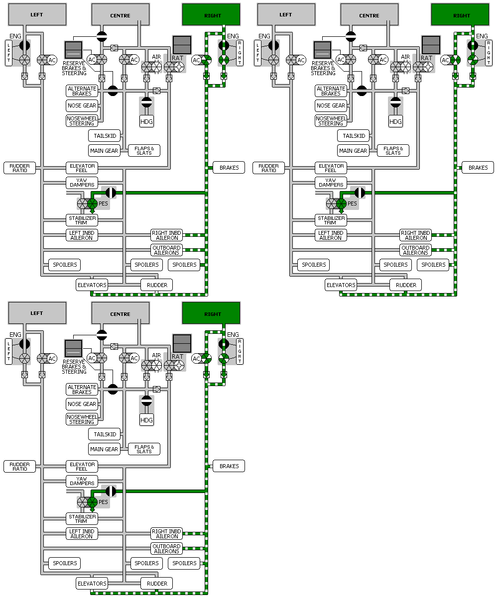
Hydraulic System - Right System 

General
The right hydraulic system is similar to the left system. The right system power:
The system consists of a reservoir, engine-driven primary pump and an electric motor-driven demand pump.
Fluid Supply
Hydraulic fluid is supplied to each hydraulic pump from an independent reservoir. The reservoir is pressurised by the Bleed Air system to ensure positive fluid flow. A quantity measuring system provides information to the EICAS status display. RF displays when a reservoir requires refilling prior to dispatch (quantity < 0.75).
![]() The RSVR light illuminates and the EICAS advisory message R HYD QTY displays when the reservoir quantity is low (quantity < 0.5). The RSVR also illuminates and the EICAS advisory message R HYD RSVR PRESS displays when the reservoir air pressure is low.
The RSVR light illuminates and the EICAS advisory message R HYD QTY displays when the reservoir quantity is low (quantity < 0.5). The RSVR also illuminates and the EICAS advisory message R HYD RSVR PRESS displays when the reservoir air pressure is low.
Fluid for the engine pump flows through a shut off valve controlled by the Right Engine Fire Switch. Putting the fire switch, shuts off the flow of fluid to the engine pump and depressurises the pump.
Engine-Driven Primary Pump
The primary hydraulic system pump is an engine-driven pump. The engine pump can be depressurised with the engine operating by turning off the engine primary pump switch.
The primary pump PRESS light illuminates and the EICAS advisory message L HYD PRIM PUMP displays when the pump output pressure is low. The pump OVHT light illuminates and the EICAS advisory message L PRIM HYD OVHT displays when the pump temperature is high.
Electric Motor-Driven Demand Pump
An electric motor-driven pump provides additional hydraulic power either on demand or continuously for periods of high system demand. The demand pump also provides a backup hydraulics power source for the engine-driven primary pump.
The pump PRESS light illuminates and the EICAS advisory message R HYD DEM PUMP displays when the pump output pressure is low. The pump OVHT light illuminates and the EICAS advisory message R DEM HYD OVHT displays when the pump temperature is high.
The Electric Demand Pump Selector sets the pump mode of operation. In the AUTO position, the pump operates when engine pump pressure is low. In the ON position, the pump runs continuously.
To reduce electrical load, the right Electric Demand Pump is inhibited on the ground during start of either engine, when only one electrical generator is operating. Right Demand Pump PRESS and SYS PRESS Lights may illuminate when starting engines on the ground.
System Pressure Indications
The SYS PRESS light illuminates and the EICAS caution message R HYD SYS PRESS displays when the hydraulic system pressure is low.
Hydraulic system pressure displays on the EICAS status page.
Reserve Brakes System
Pushing the Reserve Brakes Switch configures the hydraulic system to use the reservoir's reserve fluid, activates the electric motor-driven pump regardless of the pump switch position and isolates the pump output power to only the Normal Brakes.