Flight Controls - Stabiliser 
Stabiliser Trim Control
The stabiliser is powered by the Left and Centre hydraulic systems. Stabiliser position commands are sent to the stabiliser trim control modules, which control hydraulic power to the stabiliser through a motor and brake system. There are two modules, one for each stabiliser hydraulic source.
Note: Although the 767 has a "Mach/Speed Trim system", there are no warning lights or EICAS messages associated with it.
 The rate of trim varies and is controlled by the trim control modules. When airspeed increases, the trim rate decreases.
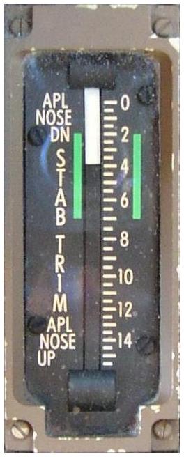
Stabiliser position is displayed on two stabiliser position indicators located on the control stand. Green bands indicate the normal trim settings for takeoff.
There are three modes of stabiliser trim control:
- electric
- alternate
- automatic
Electric Trim
Dual electric pitch trim switches located on the control wheel must be pushed simultaneously to command trim changes.
To stabiliser trim less than 1.5 units with the flaps up, requires use of the Alternate Trim system.
Alternate Trim
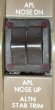 Alternate trim control is provided by the alternate stabiliser trim switches on the control stand. Pushing both switches simultaneously electrically commands trim changes and provides an increased range of stabiliser travel. The signals neutralise any other conflicting trim inputs.
Stabiliser Trim Limits
AMM In the alternate-electric-stabiliser trim mode, there are mechanical stops on the upper and lower gimbals to limit ball-screw movement. The stabiliser leading edge up limit is approximately 0.20 units of trim. The stabiliser leading edge down limit is approximately 15.30 units of trim.
Automatic Trim
The stabiliser is controlled automatically by the autopilot or by a Mach Speed Trim system when the autopilots are not engaged. The Mach speed trim system improves speed stability by trimming the stabiliser as airspeed changes. Electric, backup (Alternate), or autopilot trimming inhibits the Mach speed trim system.
Automatic stabiliser trim uses only one trim control module and trims at one-half the electric or alternate trim rate.
- LEFT A/P uses the LEFT motor.
- RIGHT A/P uses the RIGHT motor.
- CENTRE A/P uses LEFT motor (RIGHT motor if left INOP).
If two or more autopilots are engaged, both stab trim motors are used.
Mach/Speed Trim System
Non-Normal Operation
If a single autopilot is engaged, electric trimming causes the autopilot to disengage. If multiple autopilots are engaged, the electric trim switches are inhibited. Alternate trimming does not cause autopilot disengagement.
![]() The UNSCHED STAB TRIM illuminates and the EICAS caution message UNSCHD STAB TRIM displays when uncommanded stabiliser motion is detected or, with Autopilot engaged, the Stabiliser is moving opposite to the direction signalled.
The UNSCHED STAB TRIM illuminates and the EICAS caution message UNSCHD STAB TRIM displays when uncommanded stabiliser motion is detected or, with Autopilot engaged, the Stabiliser is moving opposite to the direction signalled.
The light and message also occur if alternate trim is used with an autopilot engaged.
Stabiliser Cut-Out Switches
The left and centre stabiliser cut-out switches control hydraulic power to the respective stabiliser trim control module. Placing both switches in the CUT OUT position removes all hydraulic power from the stabiliser trim control modules.
Pilot Override
The control column can be used to interrupt stabiliser trim commands by means of a Control Column operated trim cutoff switch. This feature allows the pilot to quickly stop uncommanded trim changes. The stabiliser trim commands (both electric and automatic) are interrupted if the control column is displaced in the opposing direction.
 The STAB TRIM light illuminates and the EICAS advisory message STAB TRIM displays when one of the two stabiliser brakes fails to release during trimming by the Electric trim switches; the stabiliser trim rate is one-half of the normal control wheel stabiliser trim switch rate.
If the malfunction is unique to the electric trim control, full trim rate is available by using alternate trim. If both brakes remain engaged, no stabiliser trim is available.
Pitch Enhancement System
The Pitch Enhancement System (PES) consists of a hydraulic motor in the right system driving a pump which uses trapped left trim system fluid to operate the stabiliser. It will automatically activate if both the Left and Centre hydraulic systems are lost in flight. Only electric trim is available at approximately ¼ the normal rate. Alternate and automatic trim will be inoperative.
Because the Mach/Speed Trim System moves the stabiliser at half the rate available to the pilot, its operation is barely perceptible to the pilot. Also, the stabiliser movement commanded by this system is usually small because it turns off each time the pilot trims the stabiliser and when the autopilot is engaged. The Mach/Speed Trim System is also inhibited on the ground and for twenty seconds after liftoff.
An inoperative Mach/Speed Trim System will not perceptibly affect aircraft control or handling characteristics.