Flight Controls - Flaps and Slats 
- Limitations - Flight Controls
The trailing edge flaps and leading edge slats are high lift devices that increase wing lift and decrease stall speed during takeoff, approach, and landing.
The flaps and slats are normally operated with hydraulic power from the Centre Hydraulic system.
An Alternate system allows the flaps and slats to be operated by electric motors.
Flap and slat position is controlled with the Flap Lever. Moving the lever provides signals to three Power Drive Units (PDUs) which move the flaps and slats to the selected position. One PDU drives the inboard leading edge slats, a second PDU drives the outboard slats and the third PDU drives the trailing edge flaps.
The Flap PDU is located in the left wheel well. The Slat PDUs are located in the left wing root.
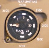 Flap and slat positions are indicated by two pointers in the flap position indicator. There are L and R pointers for the left and right wing flaps and slats. The right pointer is normally hidden from view by the left pointer.
In the flaps 1 position, only the slats move. Flaps 1, 5, 15, 20 are takeoff flap positions. Flaps 25 and 30 are landing flaps positions. Flaps 20 is used for some non-normal landing conditions.
Flap and Slat Sequencing
Flaps UP
When the flap lever is in the UP detent, all flaps and slats are commanded retracted and the flap position indicator points to UP. Moving the flap lever aft allows selection of flap detent positions 1, 5, 15, 20, 25, and 30.

- Slats UP
- Flaps UP
- Flap Position Indicator UP
Takeoff Positions
Flaps 1
Starting from flaps UP, selection of flaps 1 commands:

- the slats to move to the midrange position
- the flaps remain retracted.
The position indicator pointers move mid-way between UP and 1 when the flaps and slats are in transit. The pointers move to the 1 indication when all slats are in the midrange position and flaps reach position 1.
Flaps 5, 15 and 20
Selection of the flaps 5, 15, or 20 positions commands:

- the flaps to move to the position selected. The inboard ailerons droop in conjunction with flap extension.
- the slats remain in the midrange position.
The position indicator provides only trailing edge flap position indications for all flap settings greater than 1.
Landing Positions
Flaps 25
Selection of flaps 25 commands both the flaps and slats to move to landing positions.
- The Slats extend to the Landing position.
- The Flaps extend to 25.
Flaps 30
Selection of flaps 30 commands the flaps to extend to the primary landing position.
- The Slats remain in the Landing position.
- The Flaps extend to the primary landing position (30).
During retraction flap and slat sequencing is reversed.
Flap Gates
The flap gate at the flaps 20 detent prevents inadvertent retraction of the flaps past the go-around position. The flap gate at flaps 1 prevents inadvertent retraction of the slats.
Flap Manoeuvring Speeds
The flap manoeuvring speeds allow a normal 25° bank for manoeuvring plus an additional 15° of bank safety factor before initial buffet is encountered.
Flap Load Relief
Selecting position 25 or 30 arms a flap load relief system. If the selected flaps airspeed limit is exceeded the flaps automatically retract to position 20. The Flap Lever does not move. When airspeed is reduced, the flaps automatically re-extend.
Flap/Slat Non-Normal Operation
Alternate Flap Operation
The alternate mode allows direct manual operation of the flaps and slats through electric motors.
Alternate Flap Switches
 The alternate flaps switches:
- disable normal control
- arm the alternate mode
- engage the electric motors
- the flap lever no longer controls flaps/slats
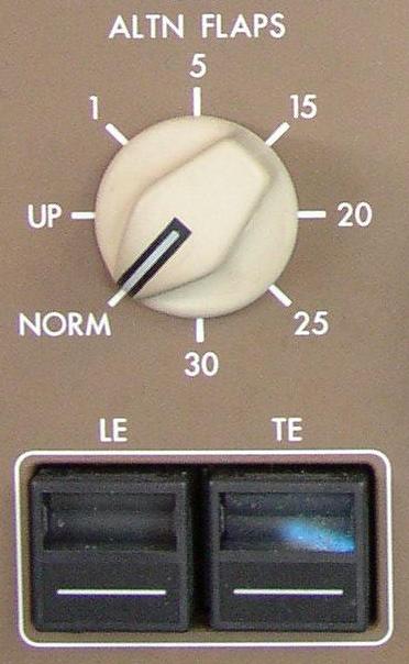
Alternate Flap Selector
The alternate flaps selector extends and retracts the flaps and slats. Alternate mode flap and slat extension is limited to flaps 20. Trailing edge flap asymmetry protection, autoslats, and flap load relief are not available in the alternate mode; however, slat asymmetry is available. Because autoslats are unavailable, the slats are fully extended at flaps 20 to improve stall handling characteristics.
- 1 - Slats extend to the midrange position, the Flaps extend to 1.
- 5 and 15 - Slats remain in the midrange position, the flaps extend to the commanded position
- 20 - The Slats extend fully, the Flaps extend to 20
Slat and flap operation time in the alternate mode is greatly increased - extension of the flaps and slats to position 20 requires approximately 3 minutes.
Leading Edge Disagreement
 The LEADING EDGE light illuminates and the EICAS caution message LE SLAT DISAGREE displays when the leading edge slat positions disagree with commanded position. The disagree indicates that the slats are not driving toward their new commanded position. Hydraulic power to both slats and flaps Power Drive Units is automatically shut off.
Note: This message may also occur if the Flap Lever is not in a detent for an extended period of time.
Leading Edge Asymmetry
The LEADING EDGE light illuminates and the EICAS caution message LE SLAT ASYM displays when the leading edge slats are not symmetrically extended. Hydraulic power to both slats and flaps Power Drive Units is automatically shut off.
Note: The leading edge Slats should not be operated using the Alternate system.
Slat Loss Sensing System
Trailing Edge Disagreement
 The TRAILING EDGE light illuminates and the EICAS caution message TE FLAP DISAGREE displays when the trailing edge flap positions disagree with commanded position. The disagree indicates that the flaps are not driving toward their new commanded position. Hydraulic power to both slats and flaps Power Drive Units is automatically shut off.
A TE FLAP-DISAGREE may also occur if the flap lever is not in a detent for an extended period of time. In this case, the light and message can be removed by moving the flap lever to the desired detent.
Trailing Edge Asymmetry
The TRAILING EDGE light illuminates and the EICAS caution message TE FLAP ASYM displays when the trailing edge flaps are not symmetrically extended. Hydraulic power to both slats and flaps Power Drive Units is automatically shut off.
Note: The trailing edge Flaps should not be operated using the Alternate system.
Load Relief Inoperative
The TRAILING EDGE light illuminates and the EICAS advisory message FLAP LD RELIEF displays when the flap load relief system fails to operate when required.
Hydraulic Driven Generator
When the Hydraulic Driven Generator is supplying electrical power, hydraulic flow to the slats and flaps Power Drive Units is reduced, resulting in increased slat and flap operation time.
Flaps and Slats Electronic Units
AMM The Flaps and Slats Electronic Unit (FSEU) consists of three physically and functionally isolated identical units. The three FSEUs monitors the output of the flap system to obtain flap system position information. Position data is used by the FSEU for asymmetry detection, uncommanded motion detection, fault annunciation, position indication, control in the alternate mode, protection in the normal mode, and flap/slat position information to other systems.
FSEU 1 performs all primary flap/slat drive protection, fault annunciation, and automatic control operations. Specifically, FSEU 1 provides:
- Uncommanded motion detection/protection of the flaps under normal control.
- Asymmetry detection/protection of the flaps under normal control.
- Trailing edge flap load relief.
- Autoslat control.
- Flaps up depressurisation.
- Logic for flap needles halfway between UP and 1.
- Fault annunciation from EICAS and TRAILING EDGE light.
- Signals to other components.
FSEU 2 performs alternate flap/slat drive protection and annunciation. Specific functions are:
- Uncommanded motion detection under alternate control.
- Asymmetry detection under alternate control.
- Autoslat control.
- Logic for flap needles halfway between UP and 1.
- Fault annunciation from EICAS and TRAILING EDGE light.
- Signals to other components.
FSEU 3 performs alternate flap/slat drive control. Specific functions are:
- Alternate electric drive motor control.
- Signals to other users