Flight Controls - Ailerons 
- Limitations - Autoflight
- Control Wheel vs Control Surface Deflection
Introduction
The roll control surfaces consist of hydraulically powered ailerons and spoilers that are controlled by rotating either Control Wheel.
Roll Control
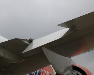 Two ailerons are located on each wing on either side of the outboard trailing edge flap. Two hydraulic actuators are used for each aileron. Aileron surface deflections are proportional to control wheel displacement. Spoilers begin to extend to augment roll control after several degrees of control wheel rotation. Control wheel forces increase as control displacement increases.
The control wheels are connected so that, if one control wheel jams, using significant force causes the control wheels to override. Roll control is then available using the free control wheel.
The inboard ailerons droop in conjunction with initial trailing edge flap extension when flap 5 is selected.
Ailerons
Aileron positions are shown on the EICAS status display. Separate pointers indicate the inboard and outboard aileron positions on each wing. A full scale deflection of the position indicator corresponds to maximum aileron travel.
Aileron Trim
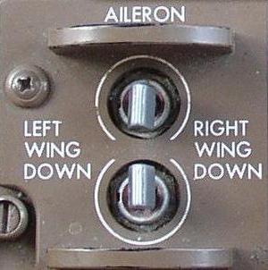 Dual aileron trim switches located on the aft aisle stand must be pushed simultaneously to command trim changes. The switches provide arming and direction signals to an electric motor that repositions the aileron neutral (trimmed) point. Hydraulic power from one of the three Hydraulic systems is necessary to accurately set aileron trim.
The amount of aileron trim is indicated on a scale on the top of each control column.
Note: If the flight crew inadvertently activates aileron trim while an autopilot is engaged, the repositioning of the aileron neutral point is not apparent to the crew. When the autopilot is disengaged, the control wheels and ailerons move to the new (possibly undesired) neutral point and the airplane will roll proportional to the amount of trim input.
Aileron Lockout
An aileron lockout control system permits full travel of the outboard ailerons at low airplane speeds and locks out the outboard ailerons at high airplane speeds. This provides the required roll authority at low airspeeds and prevents over-controlling at high airspeeds.
An AILERON LOCKOUT advisory message appears and the AIL LOCKOUT light illuminates to indicate a fault in the aileron lockout system. At high airspeeds (around cruise speeds) it may indicate that one or both of the outboard ailerons failed to lockout. When the message and light appear at low airspeeds (around approach speeds) it may indicate that one or both of the outboard ailerons failed to unlock.