Flight Controls - Rudder 
Yaw Control
Yaw control is provided by a single rudder. Two yaw dampers operate through the rudder control system to improve directional stability.
Rudder
Rudder position is shown on the EICAS status display. On the ground, a full scale indication corresponds to the maximum rudder deflection.
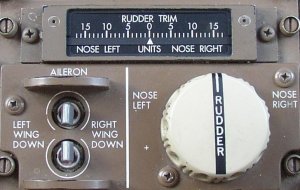
Rudder Trim
The rudder trim control can be used to command trim changes.
The rudder trim switch provides input to the trim actuator. Rotating the trim knob arms the trim motor circuit and selects either the extend mode for left rudder trim or the retract mode for right trim. The switch is powered by the Left DC Bus.
Full movement of the trim switch is required to activate the rudder trim actuator.
Rudder Trim Indicator
The rudder trim indicator shows the units of rudder trim that are commanded.
Rudder Ratio Changer
The control commands from the rudder pedals and trim control are modified by a rudder ratio changer. As airspeed increases the ratio changer desensitises these commands from the pilot to reduce the rudder deflection. Rudder response varies from approximately 26° up to 127 knots CAS to 2.5° at 410 knots CAS for full pedal travel.
AMM The rudder ratio changer system uses both Air Data Computers, both Stabiliser/Elevator Asymmetry Modules, two rudder ratio changer modules and a [single] ratio changer mechanism. The system is arranged to form two independent computation channels, each of which can provide the rudder ratio changer function.
The ratio changer receives air data computer airspeed inputs and provides control commands to an actuator powered by the Left Hydraulic system. The actuator then dampens the pilots inputs to the rudder.
![]() The RUDDER RATIO light illuminates and the EICAS advisory message RUDDER RATIO displays to indicate the rudder ratio system is failed or that control inputs to the rudder are not being correctly modified. Rudder structural protection is provided by automatic depressurisation of the Left Hydraulic system actuator which limits rudder displacement at high airspeeds. However, abrupt rudder pedal input should be avoided at high airspeeds. At low airspeeds the two remaining rudder actuators provide sufficient control for full rudder displacement.
The RUDDER RATIO light illuminates and the EICAS advisory message RUDDER RATIO displays to indicate the rudder ratio system is failed or that control inputs to the rudder are not being correctly modified. Rudder structural protection is provided by automatic depressurisation of the Left Hydraulic system actuator which limits rudder displacement at high airspeeds. However, abrupt rudder pedal input should be avoided at high airspeeds. At low airspeeds the two remaining rudder actuators provide sufficient control for full rudder displacement.
However, If the Left Hydraulic system is providing normal pressure to the ratio changer, a fault may result in limited displacement of the rudder at all airspeeds. This requires that Crosswind and Autoland limitations be observed.
- Above 160 kt, avoid large or abrupt rudder inputs.
- If normal left hydraulic pressure available:
- Crosswind limit is 15 kt.
- Do not attempt autoland.
Yaw Damping
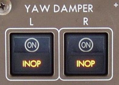 Two independent yaw damper systems improve turn coordination and Dutch roll damping and provide gust-load relief. Each system has a yaw damper controller which provides signals to operate a yaw damper actuator which in turn generates rudder control inputs. The left and right yaw damper actuators are powered by the Left and Centre Hydraulic systems respectively.
The yaw damper controllers take inputs from both Air Data Computers and all 3 Inertial Reference Units. Any operating IRS will provide the yaw rate signals for both yaw dampers.
The yaw damper INOP light illuminates and the EICAS advisory message L or R YAW DAMPER displays, when a yaw damper is inoperative. Yaw damping authority is reduced by one-half.
Autopilot Rudder Control
For autopilot control of the rudder to be active, multiple autopilots must be engaged. Confirmation that this has occurred comes with the annunciation of LAND 2 or LAND 3 on the ASA; and this cannot occur until:
- the aircraft is below 1500 ft Radio Altitude with the localiser and glideslope captured and
- no relevant equipment faults exist.
Until LAND 2 or LAND 3 is annunciated, only one autopilot is engaged and rudder control (specifically following an engine failure) must be made by the Pilot Flying.
Boeing Flight crews have reported changes in directional trim requirements which are unrelated to changes in flight conditions. Testing has shown that the 757 displays slight rudder position changes during varying phases of flight. These changes occur because of transitory temperature differences between the fin-rudder structure and the rudder control linkages. As a result, during a climb, the linkage and basic structure contract at dissimilar rates causing a left rudder shift which will require right rudder trim. As cold soaking stabilises the metallic components, the rudder will return toward the centre position. Conversely, during descent, the rudder will shift to the right which will require left rudder trim.